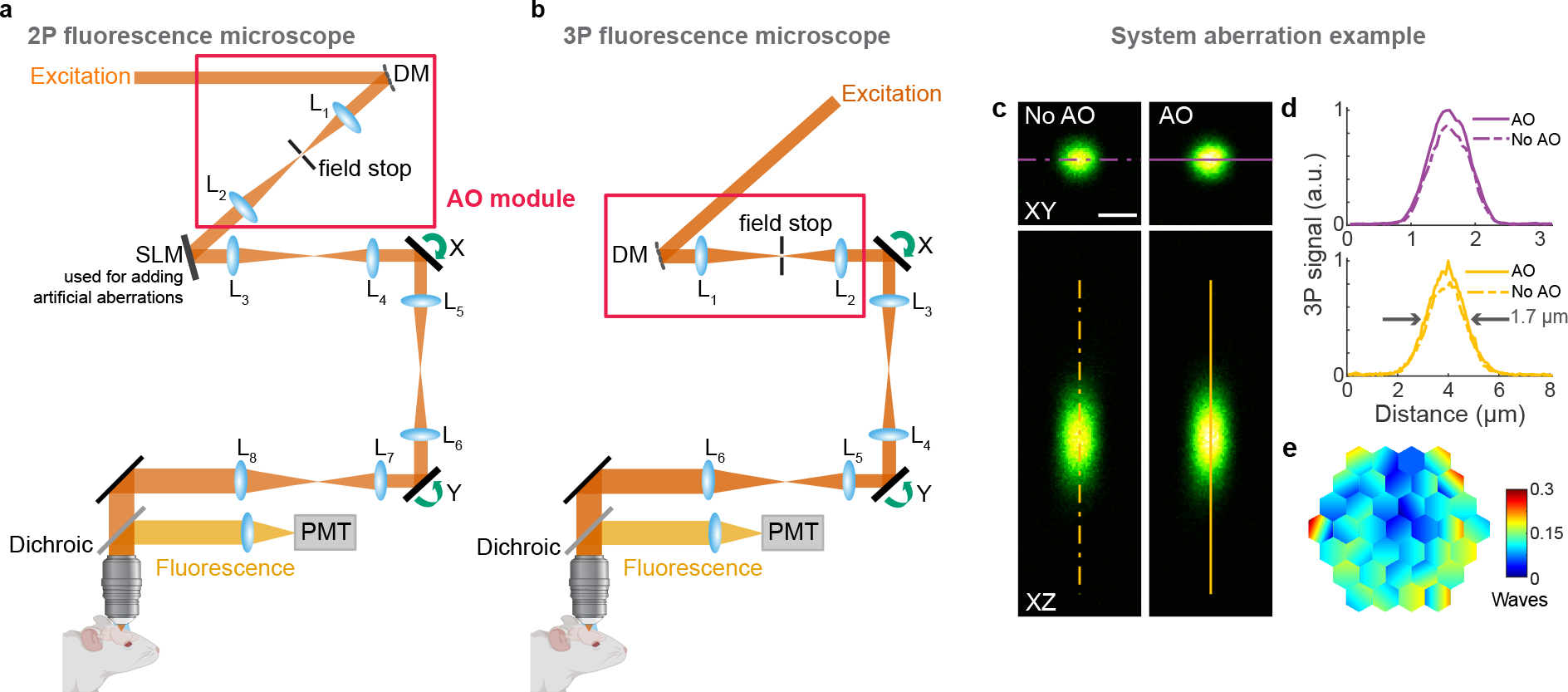
Extended Data Fig. 2 |. Schematics of AO 2P and 3P fluorescence microscopes, and example system correction.

a,b, Components of AO 2P and 3P fluorescence microscopes, respectively. DM, deformable mirror; SLM, spatial light modulator (used to introduce artificial aberration); L, lenses; X and Y, galvanometers; PMT, photomultiplier tube. c, Lateral and axial 3P images of a 1-μm-diameter red fluorescent bead, under 1300 nm excitation, taken without and with AO. Post-objective power: 0.13 mW. d, Signal profiles along the purple and yellow lines in c. e, Corrective wavefront applied to the DM. Scale bar, 1 μm. Microscope objective: NA 1.05 25×. Data representative of n>20 bead images taken during n>20 imaging sessions.
