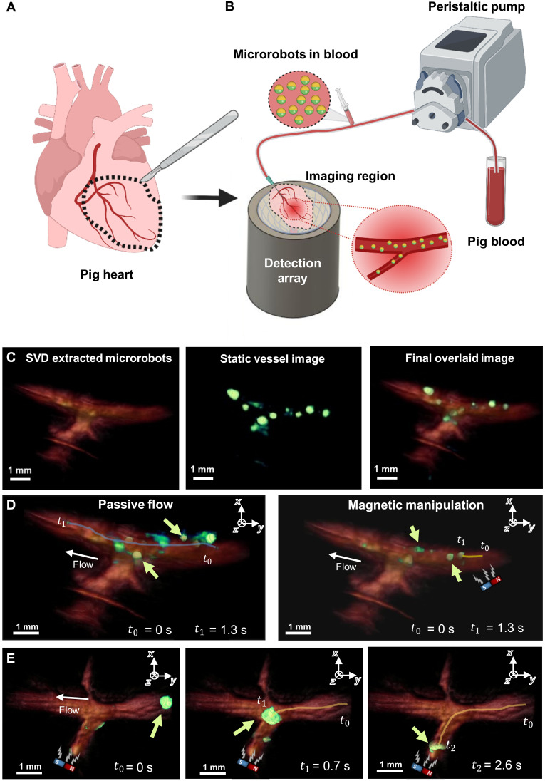
Fig. 3. OAT-based tracking and magnetic manipulation of the microrobots inside PIG phantoms.
(A) Extraction of the coronary vessels from a pig heart. The extracted coronary vessels are used as phantoms for OAT imaging of microrobots. (B) Sketch of the experimental setup. Porcine blood was pumped into the phantom using a peristaltic pump. The microrobots were added into the tubing shortly before blood entered the phantom through a needle inserted into its main vessel. Once in the phantom, the microrobots were visualized with OAT and additionally manipulated by a permanent magnet. (C) To increase the visibility of the microrobots inside the blood-filled phantom, they were separated from the blood background using an SVD-based algorithm and overlaid in a green color over red-colored blood background. (D) Motion trajectory of 20-μm-diameter microrobots (green arrow) with and without the presence of the magnetic field presence. The microrobots are presented in green color, while the porcine vessel is presented in reddish color. The microrobots experiencing no magnetic force traveled along the entire vessel length within a time interval of 1.3 s (blue curve). Microrobots experiencing the magnetic force were slowed down and traveled a much shorter distance (yellow curve). (E) Magnetic guidance of a cluster formed by 5-μm-diameter microrobots inside the PIG phantom. After their sudden release from a narrow passage outside the field of view (FOV), the microrobots (green arrow) formed a large cluster moving through the vessel. This cluster was then guided into a side vessel branch by applying force with a permanent magnet. The magnet’s position is indicated by a sketch within each image.

