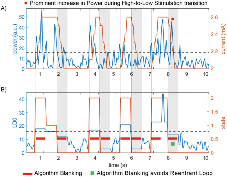
Figure 11.
Implementation of ‘fast’ aDBS in a chronically implanted patient with RC + S using optimal settings. (A) Input power feature to detector (blue trace) and corresponding transitions of stimulation current (orange trace) following power threshold crossing (dashed black line). (B) The linear discriminant LD0 (blue trace) is the averaged output of the power (blue trace is the average of 2 FFT power values in (A)). The algorithm blanking segment (lockout period) of 550 ms at the onset of a threshold cross (states 0–2 and 2–0) is depicted with a red rectangle. The detection state (orange trace) changes value with threshold crosses of LD0, with state 2 indicating a detector increase, state 1 (‘hold’) indicating LD0 within thresholds (in case upper and lower threshold) and state 0 indicating a detector decrease below threshold event. Note: after second 8, the sudden stimulation transition from high to low creates a prominent increase in power, with algorithm blanking of 550 ms or shorter (e.g. 250 ms, duration of the ramp) sufficing to avoid reentrant loop.

