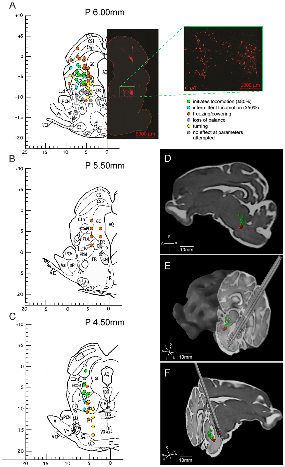
Fig. 4. Summary of stimulation sites and elicited behavioral effects.

Unilaterally stimulated electrode contact positions are overlaid on coronal slices at (A) 6 mm, (B) 5.5 mm, and (C) 4.5 mm posterior to the anterior limit of the posterior commissure on the Félix pig brain atlas [22]. The behaviors elicited with electrical stimulation were classified as shown in the legend in (A) and used to color code the electrode contact positions based on the behavior observed with stimulation. The ChAT immunohistochemistry of a matched coronal slice of the pig brainstem is included on the right side of the P 6 mm atlas slice to demonstrate the relative position of cholinergic neurons. (D) Parasagittal, (E) left oblique, and (F) right oblique three-dimensional views of effective electrode contacts for locomotion (green) are mirrored and plotted on the right side of the brainstem. The position of the cholinergic cluster of neurons representing the PPN are shown bilaterally (red) and the positions of implanted Medtronic 3389 electrodes are mirrored and plotted on the left side of the brainstem.
