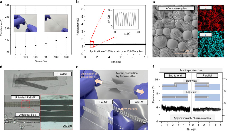
Fig. 5. Characterization of PaLMP.
a Resistance of printed PaLMP according to applied strain. b Resistance of PaLMP under repeated application of 100% strain over 10,000 cycles. c SEM image and EDS mapping of PaLMP after the strain cycles. There is no rupturing in PaLMP, and carbon and surfer contained in PSS are uniformly distributed after the cycling. d Top: photograph of folded PaLMP. Middle left, bottom right: photograph and OM images after unfolding of folded PaLMP, respectively. Bottom left: photograph after unfolding of folded bulk LM. e Top: photograph of stretched PaLMP. Bottom: images of PaLMP (left) and bulk LM (right) after stretching. f Resistance variation of multilayered PaLMP-based interconnects under repeated application of 50% strain. Inset: illustration of end-to-end (left) and parallel (right) electrodes configuration.

