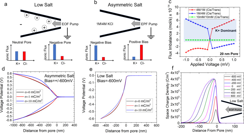
Fig. 3. Conceptual and computational model of symmetric low-salt conditions and asymmetric salt conditions.
a A graphical representation of a negatively charged glass nanopipette under low-salt conditions. When a negative voltage is applied, EOF is directed into the pore The flux imbalances for a neutral pore and a negatively charged pore (our experiments) can be found at the bottom. Negatively charged pores enable a flux imbalance in favor of cations to occur when the pore has a negative potential. b An illustrative figure displaying EPF ion pumping for asymmetric salt conditions with 1 M KCl inside the pore and 4 M KCl outside. The graphs at the bottom represent a negative and positive voltage bias with the resulting flux imbalance. c Flux imbalance calculations for symmetric and asymmetric salt conditions (both conditions where 1 M (cis)/4 M (trans) and 4 M (cis)/1 M (trans) are shown). Asymmetric salt permits the toggling of the flux imbalance with either a change in voltage or concentration gradient formation. A blue shaded region is overlaid upon the region that is K+ dominant. The symmetric low salt (10 mM/10 mM) curve is also provided in the Supplementary Information and shows that the pore is always cationic-selective. The potential distribution under d asymmetric salt conditions and e low-salt conditions for three surface charge densities (electric potential is plotted along the axis of symmetry). f Space charge density (C/m3) for the voltage range of −600 mV to +600 mV (axial distance of zero corresponds to the tip of the nanopipette). The pore diameter for this simulation was 20 nm under low-salt conditions (10 mM KCl) and the schematic illustrates EOF pump directed towards the pore.

