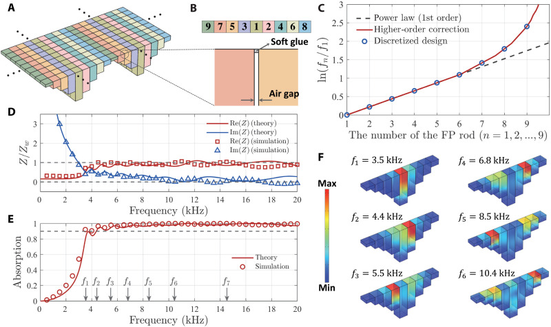
Fig. 3. Integrated FP resonator array for attaining broadband underwater acoustic absorption.
(A) Schematic of the resonator array. The dots indicate periodic repetition. (B) The nine FP resonator lengths, indicated by different colors together with an enlarged view of the air gap between two neighboring rods, with a thin layer of waterproof soft glue adhered on the top surface facing the water. (C) Design recipe of the resonance frequency distribution for realizing impedance matching. (D) The resulting real and imaginary parts of impedance, plotted as function of frequency. (E) The absorption spectrum and the first-order resonance frequencies are indicated by the gray arrows on the horizontal axis. Note that f8 and f9 are higher than 20 kHz. (F) The simulated velocity fields at different selected resonance frequencies.

