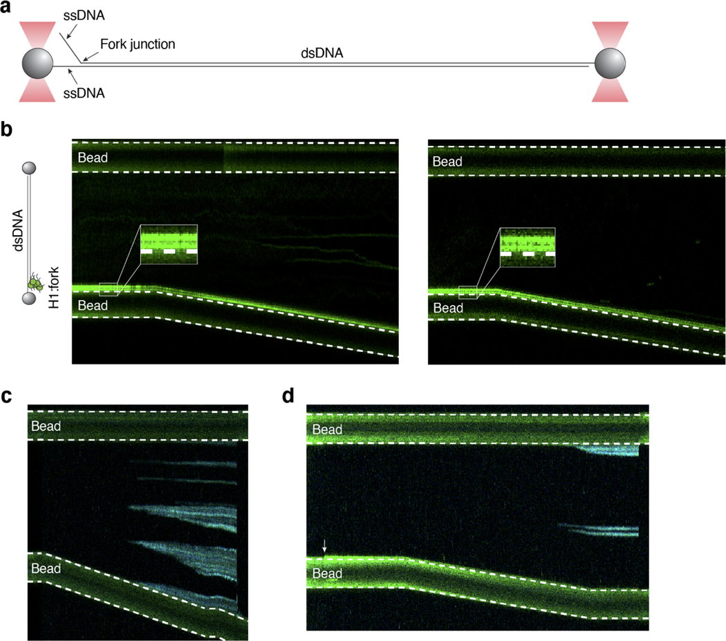
Extended Data Fig. 10. H1 interaction with forked DNA in vitro.

a, Schematic of a tethered DNA substrate containing a fork junction near one end of the tether. b, Two representative kymographs showing Cy3-H1 coalescing with relaxed ssDNA towards the fork junction near the bead. A schematic of the H1 binding configuration is shown on the left. Imaging was performed with green laser on. c, A representative kymograph showing AlexaFluor488-RPA binding to ssDNA regions formed by unpeeling from tethered ends and stochastically occurring internal nicks or by melting of dsDNA as the inter-bead distance was increased. Imaging was performed with blue laser on. d, A representative kymograph obtained with Cy3-H1 and AlexaFluor488-RPA showing that H1:ssDNA condensate (white arrow) prevents further force-induced ssDNA unpeeling at the fork junction, which would result in an expansion of RPA-bound ssDNA near the fork region. Imaging was performed with both green and blue lasers on.
