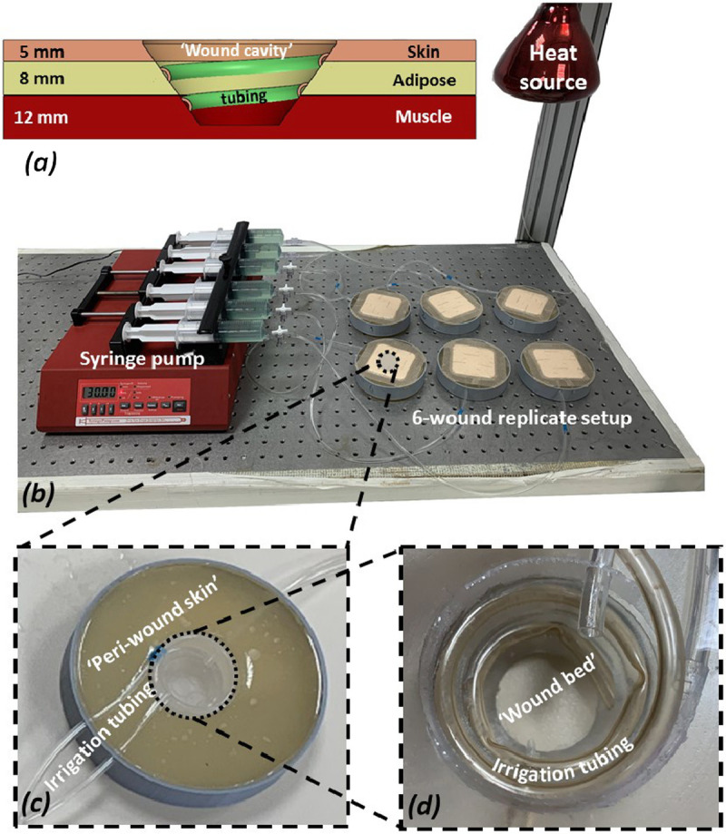
Figure 1.

THE EXPERIMENTAL SETUP AND ITS COMPONENTS
A, A scheme of a cross-section through a single “wound” simulator unit showing the different tissue simulant layers and their respective thicknesses, the shape and depth of the “wound cavity,” and the configuration of the spiral irrigation tubing. B, A photograph of the robotic phantom system including the six wound replicates and the control unit. C, A close-up view of a single simulated wound. D, Zoom on the simulated exuding “wound bed.”
