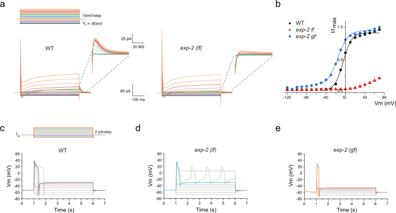
Fig. 4. Modeling of AVL action potentials.
a Simulation of voltage-clamp of AVL in the wild type (left panel) and the exp-2(lf) mutant (right panel). Top: voltage-clamp steps used in numerical simulation: holding potential is −60 mV, each step is 500 ms long in 10 mV increment. Inserts: zoomed-in view of currents from 0 to ~60 ms after returning to holding potential from serial voltage-clamp steps. b Current-voltage (I–V) relationships of normalized simulated repolarization-activated currents for WT (black squares), exp-2(lf) (red triangles), and exp-2(gf) (blue circles). WT and exp-2(gf) IV curves were fitted with Boltzmann functions (color-matching curves). c Representative action potential modeling simulations for wild-type AVL. Top: current-injection steps used in numerical simulation: each step is 5 s long in 2 pA increment. d, e Representative action potential simulations for exp-2(lf) and exp-2(gf) mutants under the same series of current-injection steps to wild-type AVL.

