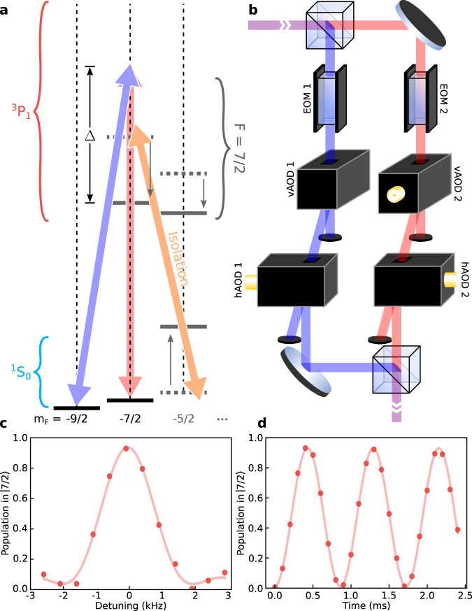
Fig. 2. Isolating and manipulating a nuclear spin qubit.
a Simplified level diagram for 87Sr showing the nuclear spin qubit states and , and how they are coupled via a two-photon Raman transition with two orthogonally polarized drive beams detuned by an amount Δ from the 3P1, F = 7/2 manifold. Also indicated is the Stark-shift beam, which is used to isolate the qubit manifold from the rest of the I = 9/2 nuclear spin manifold by shifting the leakage transition (see main text) out of resonance with the two-photon drive. b A schematic showing the preparation of the two drive beams with one electro-optic modulator (EOM) and two crossed acousto-optic deflectors (AODs) in each beam path. The EOMs are used for global, fast pulse shaping, while the pair of vertical and horizontal AODs (vAOD and hAOD, respectively) are used to adjust the phase and amplitude of each beam on a site-by-site basis. c Nuclear spin qubit resonance measured by scanning the modulation frequency of EOM1 while driving for a fixed duration of 446 μs. Note that the qubit frequency is set by the applied 11-Gauss magnetic field, which defines the quantization axis. d Rabi flops on a nuclear spin qubit, taken by setting the qubit frequency (which defines the exact drive frequency of EOM1) to 2.1 kHz and scanning the length of the drive pulse. Each data point comprises >2900 counts and is plotted with error bars representing the standard error of the mean (typically smaller than the point markers).

