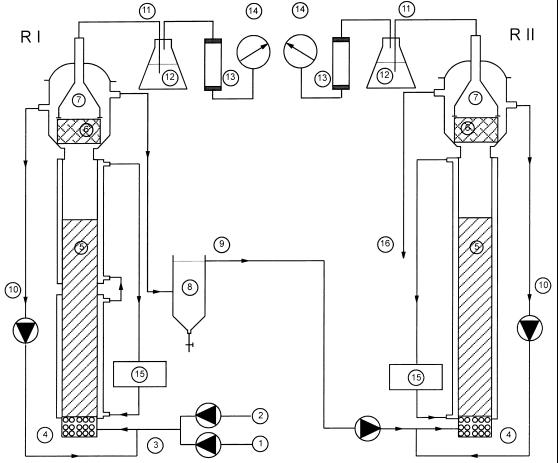
FIG. 1.
Schematic diagram of the 8.6-liter two-stage EGSB reactor system (reactors I [RI] and II [RII]) used in this study. 1, feed; 2, tap water; 3, influent; 4, stones; 5, expanded sludge bed; 6, screen; 7, gas-liquid-solid separator; 8, external settler; 9, effluent from first module = influent for second module; 10, effluent recirculation; 11, biogas; 12, sodium hydroxide (10%); 13, soda lime pellets; 14, wet test gas meter; 15, cooling bath circulator; 16, effluent from system.

