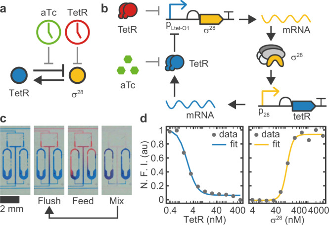
Fig. 1. Genetic oscillator circuit and experimental setup.

(a) Simple and (b) detailed circuit diagram of the synthetic genetic oscillator consisting of a negative feedback loop where σ28 acts as activator and TetR acts as repressor. Our four-variable ODE model (Eqs. (1)–(4)) considers the concentrations of the two proteins and their respective mRNAs. Protein expression is monitored via co-expression of fluorescent reporters mVenus and mTurquoise2, respectively. We can perturb the system either by inactivating existing TetR by induction with aTc, or by adding purified TetR. c A microfluidic ring reactor16 was used to maintain the reaction out-of-equilibrium by periodically exchanging a fraction of the reactor volume with fresh reagents. By switching between different input reagents, the reactions can be exposed to an arbitrary series of inputs. d Transfer curves of the two promoters determined by titrating the regulator protein in bulk. Fitted Hill parameters with 68% confidence intervals are Kh = 2.2 ± 0.2 nM, nh = 2.1 ± 0.3, Ka = 115 ± 6 nM, na = 3.4 ± 0.6. N.F.I. Normalized Fluorescence Intensity.
