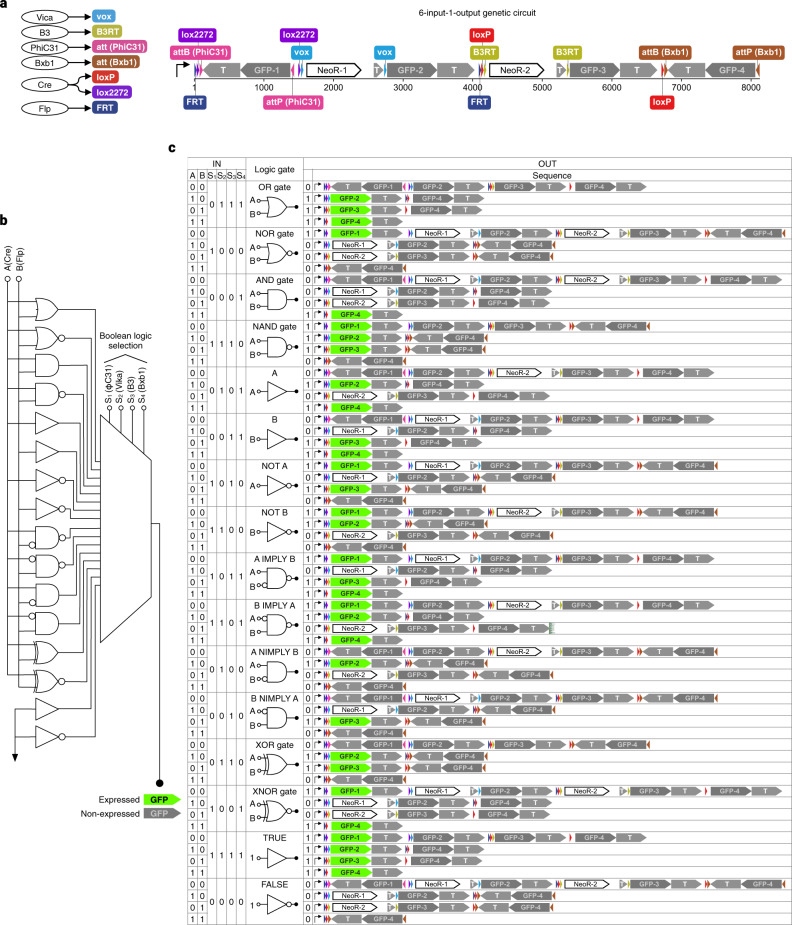
Fig. 5. Simulation of a Boolean logic LUT.
a The six-input, one-output Boolean logic LUT of the BLADE system. Left, site-specific DNA recombinases (round nodes) and their corresponding target DNA sites (round rectangles). Right, the genetic Boolean logic LUT circuit. b The wiring diagram of the genetic circuit. c Annotated DNA sequence outcomes of each signal input pattern simulated by QUEEN. GFP expresses if one of the GFP-encoding genes is placed in the same direction as the upstream promoter without being prevented by a transcription terminator.

