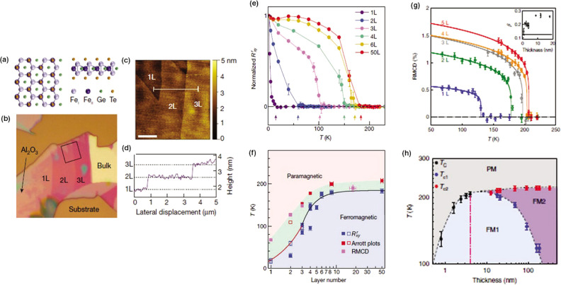
Figure 30.
(a) Atomic structure
of monolayer Fe3GeTe2. The left panel shows
the view along [001]; the right panel shows
the view along [010]. Bulk Fe3GeTe2 is a layered
crystal with an interlayer vdW gap of 2.95 Å. FeI and
FeII represent the two inequivalent Fe sites in the +3
and +2 oxidation states, respectively. (b) Optical image of typical
few-layer flakes exfoliated on an Al2O3 thin
film. (c) Atomic force microscopy image of the area marked by the
square in (b). Mono- and few-layer flakes are clearly visible. Scale
bar, 2 μm. (d) Cross-sectional profile of the Fe3GeTe2 flakes along the white line in (c). The steps are
0.8 nm in height, or consistent with the thickness (0.8 nm) of monolayer
(1L) Fe3GeTe2. (e) Normalized remanent anomalous
Hall resistance  as a function of temperature obtained from
Fe3GeTe2 thin-flake samples with varying numbers
of layers. Arrows mark the FM transition temperature Tc. (f) Phase diagram of Fe3GeTe2 as layer number and temperature are varied. Tc values are determined from
anomalous Hall effect, Arrott plots and RMCD are displayed in blue,
red and magenta, respectively. (g) Remanent RMCD signal as a function
of temperature for a sequence of selected few-layer flakes (1 L, monolayer;
2 L, bilayer; 3 L, trilayer; 4 L, four layers; 5 L, five layer). The
solid lines are least-squares criticality fits of the form α(1
– T/Tc)β. Inset: derived values of the exponent β plotted as a function
of thickness. (h) Thickness-temperature phase diagram. PM denotes
the region in which the flake is paramagnetic, FM1 that in which it
is FM with a single domain and FM2 that in which the flake exhibits
labyrinthine or stripe domains. The transition temperatures, Tc, Tc1, and Tc2, are based on the temperature-dependent RMCD or anomalous Hall effect
measurements for each flake thickness. The red dashed line denotes
the critical thickness at which a dimensional crossover occurs. All
panels are adapted with permission from ref (12). Copyright 2018 Springer
Nature.

