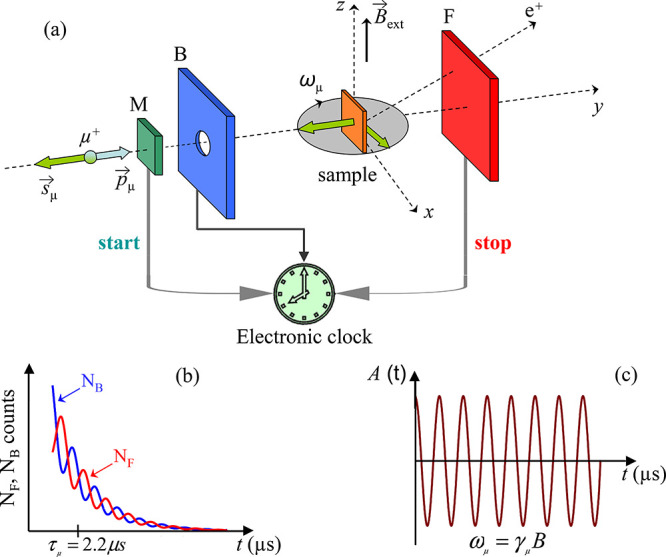
Figure 31.

Principle of a μSR experiment. (a) Overview of the experimental setup. Spin polarized muons with spin Sμ antiparallel to the momentum pμ are implanted in the sample placed between the forward (F) and the backward (B) positron detectors. A clock is started at the time the muon goes through the muon detector (M) and is stopped as soon as the decay positron is detected in the detectors F or B. Adapted with permission from ref (348). Copyright Swiss Physical Society. (b) The number of detected positrons NF and NB as a function of time for the forward and backward detector, respectively. Reproduced with permissions from ref (349). Copyright University of Zurich. (c) The so-called asymmetry (or μSR) signal is obtained by essentially building the difference between NF and NB (eq 2). All panels are adapted with permission under a Creative Common CC BY license from ref (350). Copyright 2019 MDPI.
