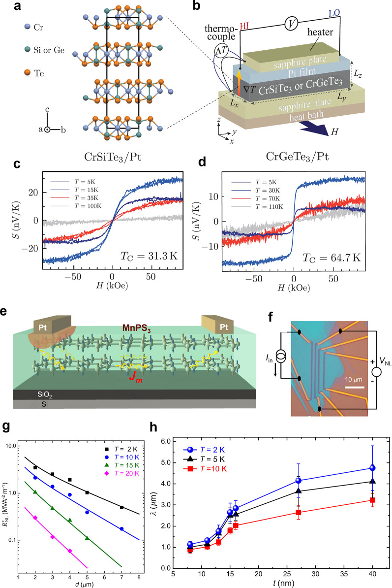
Figure 42.
Spin Seebeck effect and magnon transport
with 2D magnets. (a) Crystal
structure of CGT and CST.467 (b) Schematic
of the longitudinal SSE measurements in CST/Pt or CGT/Pt bilayers. H denotes the external magnetic field and ΔT (∇T) the temperature difference
(gradient).467 (c, d) Normalized SSE voltage S = (V/∇T) (Lz/Ly) as a function of H in the (c)
CST/Pt and (d) CGT/Pt bilayers at selected temperatures.467 Panels (a–d) are adapted with permission
from ref (467). Copyright
2019 American Physical Society. (e) Schematic of the magnon generation,
transport, and detection in MnPS3.468 (f) Optical image of the device with the MnPS3 flake and Pt electrodes, including the measurement configuration
of the nonlocal SSE.468 (g) Normalized
nonlocal signal  as a function of distance (d)
for selected temperatures in a 16 nm-thick MnPS3 flake.
The solid lines represent the best-fitting results based on a diffusion
equation.468 (h) Magnon diffusion length
as a function of MnPS3 thickness (t) for
selected temperatures.468 Panels (e–h)
are adapted with permission under a Creative Commons CC BY 4.0 license
from ref (468). Copyright
2019 American Physical Society.

