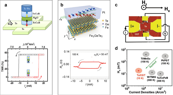
Figure 45.
2D magnet-based SOT-MRAMs. (a) Top: Schematic of a SOT-MRAM based on 3D materials507 in which an electrical current in the heavy metal (Ta) of the bottom electrode generates by SHE the vertical spin current injected in the bottom FeCoB layer. This injection of spin current switches the magnetization of FeCoB by SOT (writing). The state of the memory is detected by the TMR of the FeCoB/MgO/FeCoB MTJ (reading). Bottom: Detection by TMR of the SOT-induced switching of the magnetization of the bottom FeCoB layer in the device of the schematic.507 Adapted with permission from ref (507). Copyright 2014 AIP Publishing. (b) Top: Schematic of a bilayer for SOT-MRAM in which the orientation of the out-of-plane magnetization of a FGT layer codes the information and is switched by the SOT generated by the SHE of the Pt layer.443 As shown in the bottom part of the figure, the switching is detected by the AHE resistance Rxy derived from the voltage between transverse contacts. Adapted with permission under a Creative Commons CC BY-NC 4.0 license from ref (443). Copyright 2019 AAAS. (c) Image of a heterostructure for SOT-MRAM in which the magnetic state of a CGT layer can be switched by the SHE of a Ta layer.446 (d) Comparison of the current densities and in-plane fields required for SOT switching in devices based on 3D magnetic layers (CoFeB, MnGa, thulium iron garnet (TmIG)) and 2D magnets (FGT, CGT). The best results so far are for Ta/CGT.446 Panels (c) and (d) are adapted with permission from ref (446). Copyright 2020 John Wiley and Sons.

