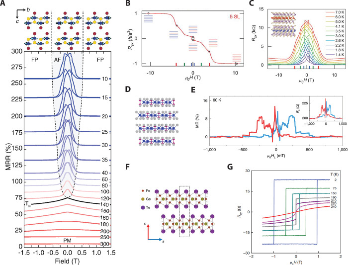
Figure 7.
Summary of intrinsic magnetoresistance in vdW magnets.
(A) Magnetoresistance
ratio MRR(B)  in bulk CrSBr versus magnetic
field (parallel to the b-axis) at various temperatures.
Each MRR curve is offset for clarity. The solid black line is an MRR
curve taken near the Néel temperature. The antiferromagnetic
(AF), fully polarized (FP), and paramagnetic (PM) phases are labeled,
and the phase boundary is denoted by dashed black lines. Schematics
showing the orientation of the spins in the AF and FP states are given
above the plot.110 Reproduced with permission
from ref (110). Copyright
2020 John Wiley and Sons. (B) Ryx of a 5-layer MnBi2Te4 sample as a function
of external magnetic field applied perpendicular to the sample plane
at T = 1.6 K. Data are symmetrized to remove the Rxx component.111 (C) Rxx of
a 5-layer MnBi2Te4 flake as a function of magnetic
field acquired at various temperatures. Data are symmetrized to remove
the Ryx component. Inset
shows the layered crystal structure of MnBi2Te4 in the AF state.111 Panels (B) and (C)
are reproduced with permission from ref (111). Copyright 2020 AAAS. (D) Ball and stick model
of the Cr2Ge2Te6 crystal structure.86 (E) Magnetoresistance
  curves
for T = 60 K and
back-gate voltage of 3.9 V for a 22 nm-thick Cr2Ge2Te6 flake. The background is removed for clarity.
The magnetic field is applied in the out-of-plane direction. Unprocessed
data are shown in the inset.86 Panels (D)
and (E) are reproduced with permission from ref (86). Copyright 2020 Springer
Nature. (F) Side view of the atomic lattice of bilayer Fe3GeTe2. The dashed rectangular box denotes the crystal
unit cell.77 (G) Temperature-dependent
magnetic field (out-of-plane) sweeps of the Hall resistance measured
on a 12 nm thick Fe3GeTe2 flake.77 Panels (F) and (G) are reproduced with permission
from ref (77). Copyright
2018 Springer Nature.

