
Figure 18.
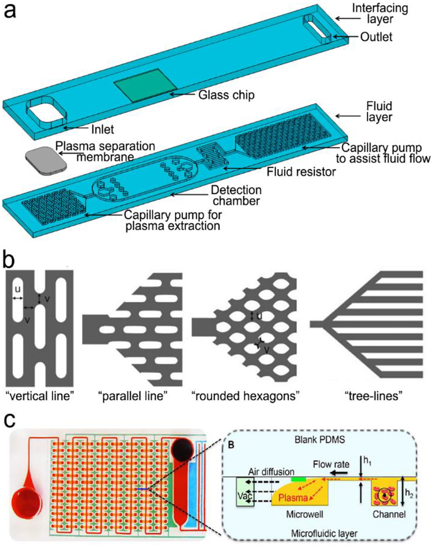
(a) Basic structure of plastic-/glass-based lateral flow device. It is composed of interfacing layer (cover layer) and fluid layer. The fluid layer contains four main functional zones, including a pretreatment unit (plasma separation and extraction), a detection chamber, a fluid resistor and a “built-in” micropump. (b) and (c) examples of “built-in” micropumps: (b) capillary pumps such as “vertical lines”, “parallel lines”, “rounded hexagons” and “tree lines”. (c) A pneumatic pump fabricated by multiple vacuum pillars. Reproduced with permission from (a) ref. 272, copyright 2017, MDPI; (b) ref. 273, copyright 2007, The Royal Society of Chemistry; (c) ref. 274, copyright 2017, The Royal Society of Chemistry.