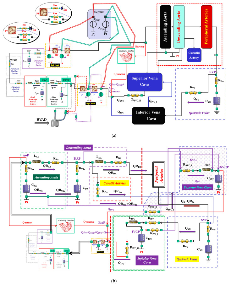
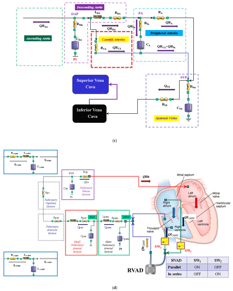
Figure 1.
(a) Electric analogue of the cardiovascular system. The network is assembled with septum, left and right heart, main and small pulmonary arterial sections, pulmonary arteriole and capillary sections, and the pulmonary venous section. The left circulation includes ascending and descending aorta compartments, peripheral arteries, and carotid artery sections, coronary circulation, superior and inferior vena cava sections, and systemic veins compartment. RVAD is the right ventricular assist device. Table 2 lists the symbols used. (b) The behaviour of the ascending aorta is simulated with resistances RAA and RVaa, inertance LAA and compliance CAA. QRAA is the flow through the resistance and inertance. The descending aorta is implemented with resistances RDA and RVda, inertance LDA and compliance CDA. QRDA is the flow through the resistance (RDA) and inertance (LDA). The carotid arteries section is reproduced with a simple resistance (RCA). The superior vena cava module consists of resistances RSVC_I and RSVC_II, inertance LSCV, and compliance CSVC. The inferior vena cava module is modelled with resistances RIVC, RIVC_I, and RIVC_II; inertance LIVC; and compliance CIVC. The intrathoracic pressure (Pt) affects compliances CAA, CDA, CIVC, and CSVC. Table 2 lists the symbols used. (c) The peripheral arteries module is modelled with resistances RA and RVa and compliance CA. The resistor RVa accounts for viscous losses of the vessels wall. QRA is the blood flow outside the compartment; it is a part of the blood that reaches the systemic veins compartment. (d) Schematic representation of RVAD connection. When the right ventricular assist device is connected in parallel, blood is removed from the right atrium (SW1 = ON and SW2 = OFF) and ejected into the pulmonary artery. When RVAD is connected in series, blood is removed from the right ventricle (SW1 = OFF and SW2 = ON) and ejected into the pulmonary artery. The input (output) RVAD cannula is modelled with RLC elements. QoPUMP (QiPUMP) is the output (inlet) flow rate from the pump. QoCANN (QiCANN) is the output (inlet) flow rate from the cannula. The electrical analogue of the pulmonary circulation is described in [22] (Reprinted with permission from Ref. [22], Copywright© 1991–2019 C. De Lazzari).


