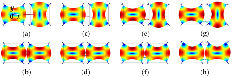
Figure 8.
WG modes of a 2-DoF coupled BAW square plate resonator system with the same mechanical coupling beam located at different positions (represented by y) simulated in COMSOL. (a) Out-of-phase WG mode, y = 0 μm; (b) In-phase WG mode, y = 0 μm; (c) Out-of-phase WG mode, y = −100 μm; (d) In-phase WG mode, y = −100 μm; (e) Out-of-phase WG mode, y = −200 μm; (f) In-phase WG mode, y = −200 μm; (g) Out-of-phase WG mode, y = −300 μm; (h) In-phase WG mode, y = −300 μm. Note: y represents the y-axis value of the center location of the coupling beam, and the origin is at the center of the first square-plate proof mass. Note: There is a coordinate system in (a) with the original point set at the center of the left resonator. The y-axis value shows the position of the coupling beam. When the coupling beam is in the center position of both two resonators, y = 0. Then the beam moves down to the edge part, the y axis value is −100 μm, −200 μm, and −300 μm, respectively.

