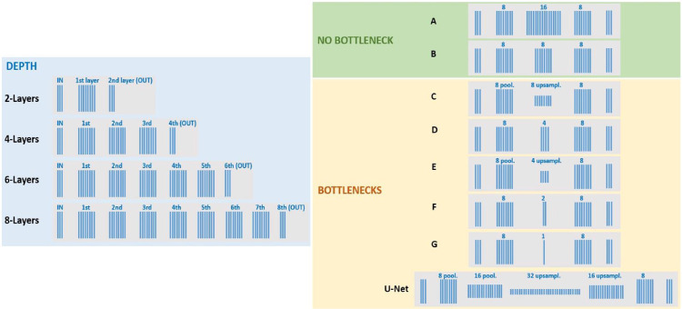
Figure 4.
Architectures. (Left) Range of architectures of different depth following the basic structure of the nets studied in Gomez-Villa et al. (2019, 2020): three channels at the input and at the last (output) layer. In this work the input is in an LMS color representation. The rest of the layers have eight features with no undersampling or bottleneck, as represented by the eight blue lines of the same length. These architectures of increasing depth are used to study the compensation of the biodistortion in images and videos. The best of these architectures in terms of CSFs (which turns out to be the two layers example) is used with images to explore chromatic adaptation. (Right) Range of architectures used to illustrate the effect of bottlenecks. In this case, the inner layer in the four layer architecture at the left is systematically expanded (in A) or contracted (from C to G, either in the number of features or in the spatial resolution. See numbers and indications of pooling/upsampling and corresponding length of the layers-) to generate a range of bottlenecks. Finally, an illustrative U-Net with no residual connections is also considered in the experiments with bottlenecks.

