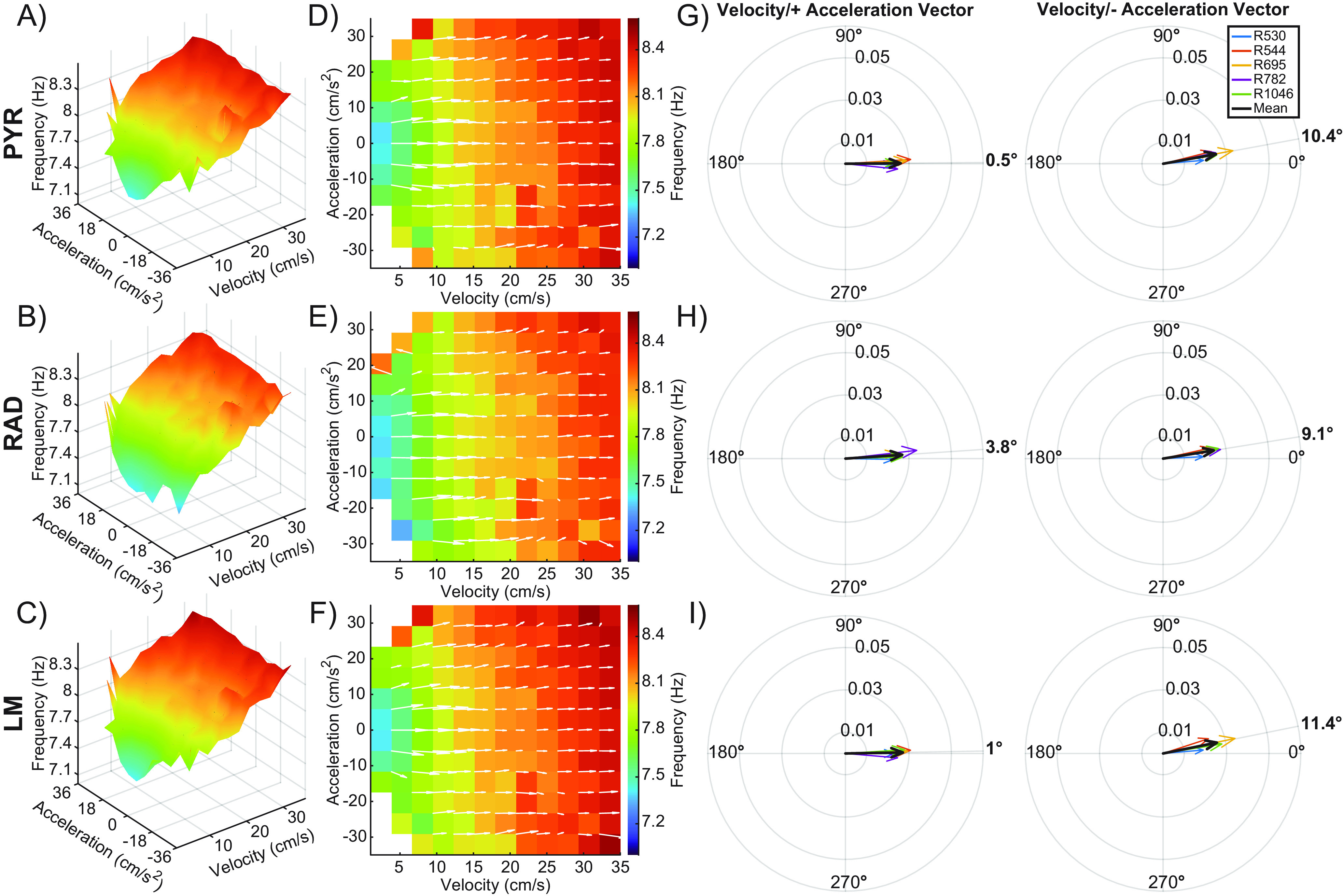
Figure 7.

Velocity and acceleration modulation of theta frequency during the alternation task. A–C, Note that this figure is the same as Figure 6, but for a theta frequency rather than power. 3D plots showing the interaction between velocity, acceleration, and theta frequency for the stratum pyramidale (PYR; A), stratum radiatum (RAD; B), and the stratum lacunosum moleculare (LM; C) across all animals. D–F) 2D figures representing the top-down view of the 3D surface. Overlaid white arrows show the direction and magnitude of the local slope for each possible velocity and acceleration bin combination. G–I, Compass plots showing the average of the slope vectors (white arrows) from plots D–F. An average vector was generated for both the positive and negative acceleration halves of each plot. The average of each animal is shown in various colors, with the cohort mean shown in black. The angle of the cohort means are shown in bold outside of each compass plot. Note that vector angles close to 0° indicate that LFP frequency was primarily modulated by velocity. As the vector angle increases toward 90°, acceleration makes more of a contribution.
