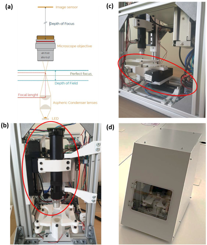
Figure 1.
(a) Schematic diagram of the Schistoscope optical train (b) Region of interest showing the Z-axis consisting of a mechanical slider and optical setup (c) Region of interest showing the sample stage mounted on the X and Y slider mechanism (d) Exterior of the Schistoscope device (embodiment).

