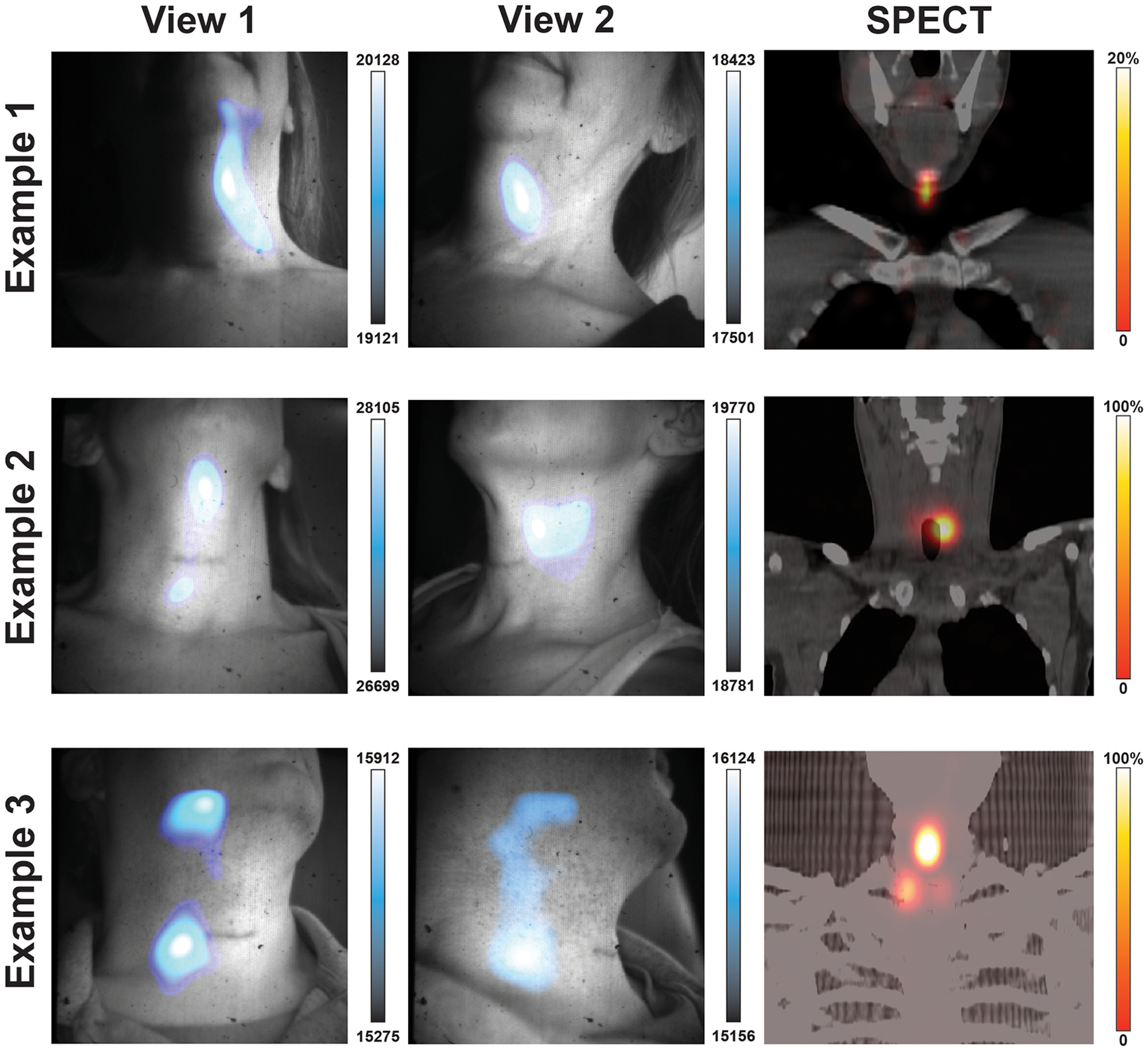
ED Fig. 3. Additional patient images with alternate CLI projections.

131I-Iodine patients were imaged head on and from the side. Example 1 shows images from two angles with CLI focal intensity in the patients left neck before the muscular triangle with corresponding SPECT image showing uptake near the submental triangle. In Example 2 CLI images show intensity regions below the submental triangle and before the submandibular triangle while the corresponding SPECT scan shows the iodine uptake to be located deeper in the neck below the submandibular triangle adjacent to the trachea. In Example 3, two focal regions of CLI are seen between projections with the reduction of the upper CLI region in View 2. The corresponding SPECT scan shows three lesions with the brightest lesion to the right of the patient midline and below the submental triangle. Here CLI shows in example 3 the most avid lesion in the midline, though the upper CLI spot appears to be an artifact that dissipated in the second view. Overall, the most iodine avid region in the field of view was where the most intense CLI signal was seen, with the exception of the artifact seen in View 1 of Example 3 which dissipated in View 2. Possible sources of artifact light include insufficient time (< 5 minutes) to let the light from the patient and enclosure dissipate along with residual charge on the sensor, as well as patient movement.
