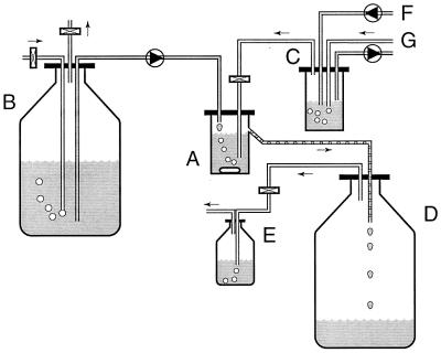
FIG. 1.
Schematic diagram of the continuous gas flow chemostat used for enrichment and isolation of Methanomethylovorans hollandica DMS1T. Medium was pumped into the culture vessel, resulting in a dilution rate of 0.005 to 0.02 h−1. The energy and carbon source for growth was added via the gas stream bubbling through the chemostat. An oxygen-free N2-CO2 gas stream was passed through a regulation vessel. DMS from a stock solution was pumped into this vessel. The DMS was then sparged out of the water phase, and the DMS-containing gas was then passed through the culture vessel. The concentration of DMS in the incoming gas could be regulated by altering the N2-CO2 gas flow or the pump flow rate of the DMS stock solution. In this way, the dilution rate and the concentration of DMS to which the culture was exposed could be regulated independently. A, culture vessel; B, medium stock preparation; C, regulation vessel; D, waste vessel; E, gas trap bottle; F, tubing connected to a DMS stock solution; G, tubing connected to an oxygen-free N2-CO2 gas stream (0.3 atm). Shaded tubing is tubing that contained liquid. Tubing with droplets is tubing that contained both gas and liquid, whereas tubing without shading or droplets is tubing that contained gas. Rectangles represent sterile (gas) filters. Circles represent peristaltic pumps; the triangles in the circles indicate the direction of pumping. The arrows indicate the direction of the gas flow.

