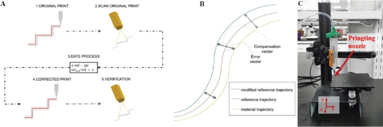
Figure 2.

Schematic illustration of the process control principle for helix trajectory detection and correction. (A) Five steps from process control to identification and correction of helix trajectory. (B) Example of normal vector approach to compensate the error vector of the reference trajectory by mirroring to obtain a new modified reference trajectory. (C) Extrusion-based bioprinting machine with standard Cartesian coordinates.
