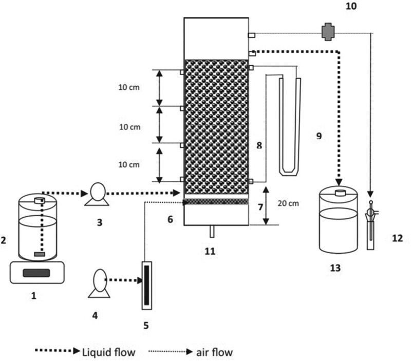
Figure 6.

Schematic diagram representing the submerged aerated biofilter setup for the treatment of volatile organic compounds in pharmaceutical wastewater. (1) Magnetic stirrer, (2) Influent tank (3) Peristaltic pump, (4) Aquarium air pump, (5) Airflow meter, (6) Air inlet port, (7) Diffuser arrangement, (8) Packing media, (9) Manometer, (10) Connector for gas sampling, (11) Liquid drainage port, (12) Impinger, (13) Effluent collection tank [128].
