Abstract
Vascular smooth muscle cells align circumferentially around the vessel lumen, which allows these cells to control vascular tone by contracting and relaxing. It is essential that this circumferential alignment is recapitulated in tissue engineered blood vessels. While many methods have been reported to align cells on 2D polymeric substrates, few techniques enable cell alignment on a 3D physiologically relevant hydrogel substrate. We hypothesized that the ridges inherent to the sides of fused deposition modeling 3D printed molds could be used to topographically pattern both stiff and soft substrates and thereby align cells on flat and curved surfaces. Flat and curved molds with 150, 250, and 350 μm ridges were 3D printed and used to topographically pattern polydimethylsiloxane and gelatin-methacryloyl. The ridges transferred to both substrates with less than 10% change in ridge size. Vascular smooth muscle cells were then seeded on each substrate, and nuclear and actin alignment were quantified. Cells were highly aligned with the molded ridges to a similar extent on both the stiffer polydimethylsiloxane and the softer gelatin-methacryloyl substrates. These data confirm that fused deposition modeling 3D printed molds are a rapid, cost-effective way to topographically pattern stiff and soft substrates in varied 3D shapes. This method will enable investigators to align cells on 3D polymeric and hydrogel structures for tissue engineering and other applications.
Keywords: Vascular smooth muscle cells, Cell alignment, Hydrogel patterning, 3D printing
1. Introduction
Cell alignment is an essential feature of many different tissues in the body including the corneal stroma, tendons, bone, skeletal muscle and smooth muscle [1]. In the vascular system, smooth muscle cells (SMC) are aligned circumferentially about the vessel lumen. This alignment allows SMC to constrict and dilate the vessel when they contract and relax, respectively, which is vital to controlling vascular tone. When SMC alignment is lost in vascular diseases such as atherosclerosis, SMC can no longer perform their normal contractile function [2]. Therefore, recreating circumferential SMC alignment in vitro is essential for tissue engineering blood vessels as well as for investigating SMC function.
A wide variety of methods have been used to align cells on flat, two-dimensional (2D) substrates, including physical stimuli such as electrical fields [3] and mechanical forces such as shear stress [4, 5] and uniaxial cyclic tensile strain [6, 7]. Cells can also be aligned on flat substrates by micropatterning lines of adhesive polystyrene [8], fibronectin [9], or collagen [9] or by creating topographically patterned grooves and ridges on polymers to align fibroblasts [10], endothelial cells [10], and vascular stem cells [11]. SMC in particular have been aligned by orienting electrospun fibers [12], by micropatterning adhesive lines [13–16], by microfabricating grooves or channels in polydimethylsiloxane (PDMS) and other polymers [15, 17–20], or by bioprinting gelatin lines to create channels [21].
While cell alignment has been widely studied on flat substrates [22], in vivo most cells are aligned on surfaces with three-dimensional (3D) features. SMC, for example, are aligned circumferentially around a cylindrical tube. Cell alignment on 3D surfaces requires more complex methods. In some cases, patterns have been created by UV patterning or electrospinning nanofibers on the surface of 2D flexible or shape memory polymer films that were then shaped into cylindrical tubes [18, 23]. Patterns have also been created on the surface of cylindrical structures by electrospinning polymers or printing gelatin channels directly onto the cylindrical tubes, or by extruding gelatin- methacryloyl (GelMA) though a grooved PDMS channel [12, 21, 24]. Microchannels to align SMC have been created within a polymeric scaffold by sacrificial molding of melt spun circumferentially oriented sugar fibers [25]. More recently, SMC aligned on circumferential microwrinkles that were created on the inner surface of semi-cylindrical PDMS structures by stretching the PDMS and treating it with UV light before allowing it to relax [26].
While these techniques enable SMC patterning on cylindrical structures, they often only work on stiff, synthetic polymers and are complex to achieve. Fused deposition modeling (FDM) is a relatively inexpensive and accessible 3D printing technique. In FDM, parts are fabricated by melt extruding plastic filament in a layer-by-layer fashion. This process leads to inherent ridge features on the 3D printed part surfaces. We hypothesized that these 3D printed ridges could be used to topographically pattern both stiff and soft substrates and thereby align cells on flat and curved surfaces.
2. Material and methods
2.1. 3D printed mold fabrication
All molds were printed using an Afinia H400 3D printer programmed to print 150 μm, 250 μm, and 350 μm layer thicknesses. 10 mm cubes were created to pattern flat PDMS surfaces. 10 × 10 × 1.5 mm square molds were designed to pattern flat GelMA surfaces. 10 mm long semi-cylinders (10 mm diameter) were created to topographically pattern curved surfaces. The semi-cylinders were printed with the cylinder axis perpendicular to the 3D printing build plate to create alignment features on the curved mold face. All 3D printed molds were printed using polylactic acid (PLA, Afinia, 25267) filament.
2.2. PDMS patterning
Polydimethylsiloxane (PDMS, Dow, Sylgard 184, 1673921) was mixed in a 10:1 elastomer base to curing agent ratio. A foundational PDMS slab was first formed by adding 11 g wet PDMS to a 100 mm dish and curing at 80 °C overnight. An additional 5 g wet PDMS was then poured onto the slab. The patterning surfaces of the 3D printed molds were also coated with wet PDMS. The molds were inverted onto the wet PDMS on the slab, and the entire culture dish was placed in a desiccator for 30 min to degas the PDMS. Any remaining air bubbles were manually removed, and the samples were cured at 80 °C for 3 h. The 3D printed molds were then manually separated from the PDMS, leaving patterned flat and curved PDMS surfaces. PDMS samples were UV sterilized for 90 min, plasma cleaned for 1 min (Harrick, PDC-001), and coated with 50 μg/mL rat-tail collagen (Gibco, A1048301) for 3 h at 37 °C.
2.3. GelMA synthesis and patterning
To synthesize gelatin methacryloyl (GelMA), 10% w/v Type A porcine gelatin (Sigma Aldrich, G2500) was dissolved in phosphate-buffered saline (PBS, Gibco) at 50 °C. 7.6% v/v methacrylic anhydride (MA, Sigma Aldrich, 276,685) was added dropwise to the gelatin solution over the course of 90 min. The solution was centrifuged at 1000 rpm for 2 min to pellet unreacted MA. The supernatant was then diluted with an equal amount of PBS and dialyzed over two days using a dialysis cassette (Thermo Scientific, 66,830) submerged in deionized water at 50 °C. After dialysis, the solution pH was adjusted to 7–7.4 using 1 M NaOH. The solution was then lyophilized (Labconco, 700611000) for 5 days.
To create GelMA hydrogels, lyophilized GelMA was UV sterilized for 30 min and then dissolved in PBS (10% w/v) at 50 °C. 0.05% w/v photoinitiator (lithium phenyl-2,4,6-trimethylbenzoylphosphinate; LAP) was added. For patterned GelMA samples, 300 - 400 mL GelMA-LAP solution was loaded onto the corresponding 3D printed mold, which was placed inside a 3D printed square well to keep the solution in place during UV crosslinking. The GelMA-LAP solution was UV crosslinked using 254 nm light (Analytik Jena, 95–0230–01) for 15 min. The 3D printed molds were then manually separated from the GelMA hydrogel.
2.4. Smooth muscle cell culture and seeding
Human coronary artery smooth muscle cells (SMC, Lonza, CC-2583) were maintained in Smooth muscle Growth Medium (SmGM-2, Lonza, CC-3182) supplemented with 10% fetal bovine serum (HyClone, SH30071.03), 1% penicillin-streptomycin (Gibco, 15,140,122), and 1% l-glutamine (Gibco, 25030-081). Media was replaced every other day, and cells were used between passage 4 and 8. To seed cells on topographically patterned surfaces, SMC were detached from the culture dish with trypsin-EDTA (Gibco, 25,200,056), counted using a Countess automated cell counter (Thermo Fisher Scientific, AMQAX1000), and resuspended in SmGM-2 at 5 × 10⁶ cells/mL.
2.5. Cell fixation and imaging
Samples were washed with cold PBS and fixed with 4% paraformaldehyde (PFA, Invitrogen, FB002) for 15 min on ice. After thorough washing in PBS, cells were permeabilized with 0.1% Triton X-100 (Alfa Aesar, A16046-AP) for 5 min followed by two additional PBS washes. Non-specific binding was blocked by incubating samples with 1% bovine serum albumin (BSA, Sigma Aldrich, A9418) for 30 min. Cells were labeled with 1:2000 Hoechst (Invitrogen, H3570) and 1:80 rhodamine phalloidin (Biotium, 00027) to label nuclei and actin, respectively, for 30 min at room temperature. Samples were then imaged using a Nikon Eclipse Ti2-E confocal laser scanning microscope at 10x and 40x magnification with 2.5 μm and 0.5 μm step sizes, respectively. Maximum intensity projections were used for quantification.
2.6. Alignment quantification
Actin alignment was quantified using MatFiber software, which was developed in MATLAB and originally used to quantify collagen fiber orientation in myocardial scar tissue in rats after myocardial infarction [27]. Briefly, the software divides an input image into square subregions (40 × 40 pixels). Each subregion is assigned a vector based on an intensity gradient detection algorithm [28]. The vector angles are collected into histograms, which are then used to quantify the overall image orientation. For all alignment quantifications, a maximum intensity projection of the actin channel z stack was adjusted for brightness and contrast. Then a black and white image of the adjusted actin projection was exported to MATLAB allowing for analysis. Nuclear alignment was quantified using ImageJ (NIH). An intensity threshold was manually applied to the maximum intensity projection of the nuclei channel z stack for each image. The threshold was selected to facilitate nuclear edge detection by including the maximum number of nuclei as distinct particles while minimizing extraneous particles and background fluorescence. A watershed operation was then used to separate adjacent nuclei. For all 40x images, the fill holes command filled in empty space in nuclei missed by the intensity threshold. Nuclear angles were then determined by generating an ellipse for each particle using the Analyze Particles command, which also determined the ellipse long axis angle [22].
Using MATLAB, actin and nuclear angles were plotted in histograms to visualize angle frequency. Overall alignment was compared among groups by calculating the average of the angle absolute values. Because the angles ranged from −90° to 90°, the angle absolute value was required to avoid the average angle being near zero due to equal numbers of positive and negative angle values. The kurtosis of the angle frequency data was also quantified to compare alignment among samples.
2.7. Statistics
MATLAB was used for all statistical analyses. Student’s t-test was used to individually compare patterned groups to the corresponding unpatterned control group. Data are shown as mean ± standard deviation. At least three data points (images) were acquired per sample.
3. Results
3.1. 3D printed molds and PDMS patterning
The objective of this study was to determine if the 3D printed ridges on the sides of FDM 3D printed parts could be used to pattern both stiff and soft substrates to topographically align cells on flat and curved surfaces. We therefore created 3D printed molds in two forms (flat and curved) and with three programmed layer thicknesses set in the 3D printing software (150, 250 and 350 μm). We first confirmed that the 3D printed mold ridge thickness was similar to the programmed layer thickness, and that the mold ridge thickness transferred accurately to PDMS. The measured ridge size for both 3D printed molds and PDMS samples deviated by less than 10% from the programmed ridge thicknesses, irrespective of the ridge size or mold shape (Fig. 1; sample images in A; quantification in B). These data show that ridges of defined size can be consistently formed on FDM 3D printed flat and curved molds, and that these ridges can be transferred to PDMS.
Fig. 1.
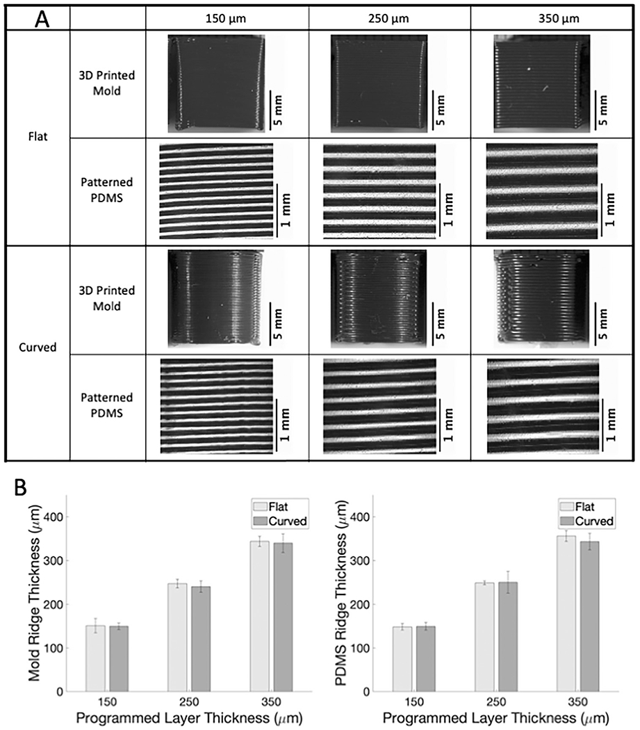
Ridge patterns on 3D printed molds can be successfully transferred to PDMS. (A) Images of 3D printed PLA molds and corresponding patterned PDMS samples acquired with Nikon SMZ745T. (B) Measured ridge thickness versus 3D printer programmed ridge thickness for 3D printed molds (left) and PDMS samples (right).
3.2. Cell alignment on PDMS
We next seeded SMC on flat unpatterned and patterned PDMS surfaces and quantified cell alignment. SMC on flat unpatterned PDMS samples showed no alignment, with nuclear and actin angular frequency evenly distributed (Fig. 2; sample confocal microscopy images with corresponding nuclear and actin angle histograms in A; average angle and kurtosis for all samples in B). The average nuclear and actin angle was around 45° for SMC on flat unpatterned PDMS, and the kurtosis was less than two. In contrast, SMC on flat ridged PDMS demonstrated alignment in the ridge direction. Average nuclear and actin angles were 13–20° for all ridge thicknesses, which was statistically significantly lower than the average angles for SMC on unpatterned PDMS. Similarly, the kurtosis of the nuclear and actin angle distributions increased to around 4 or around 10 for nuclei and actin, respectively, indicating a more peaked angle distribution.
Fig. 2.
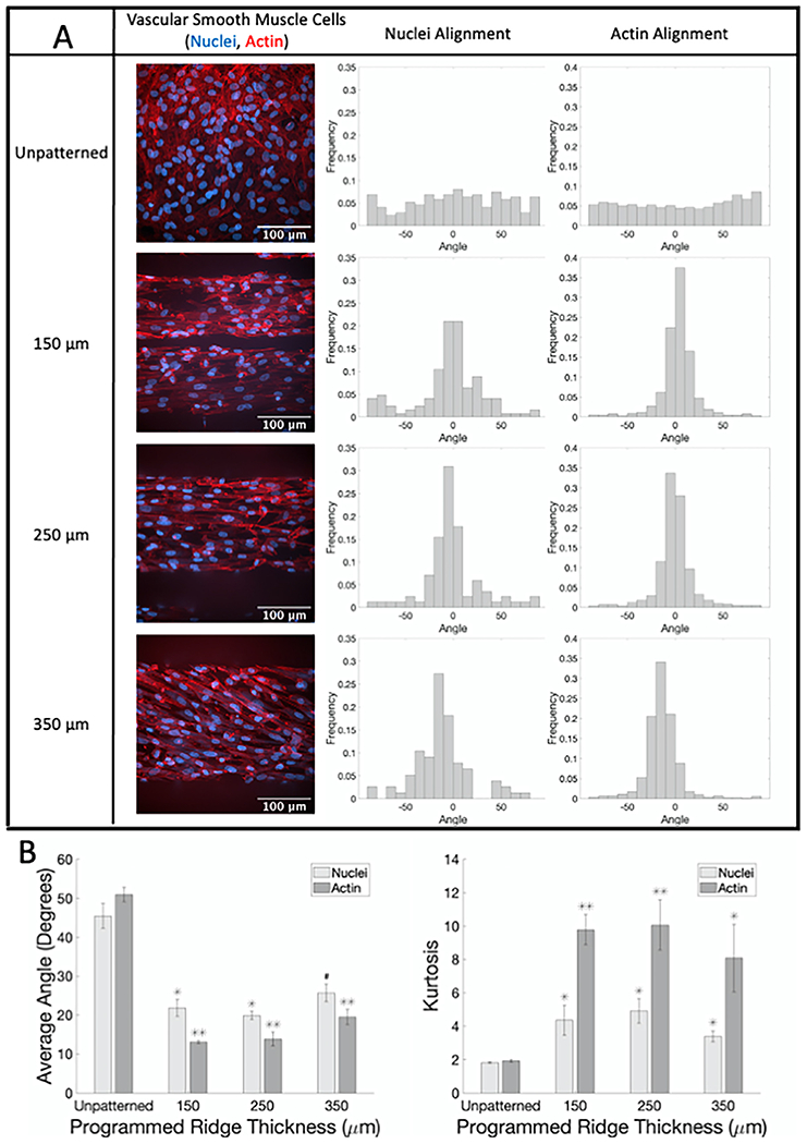
SMC show significant alignment when seeded on flat PDMS patterned with different ridge thicknesses compared to unpatterned samples. (A) Representative confocal microscopy images of SMC on flat PDMS labeled for actin fibers (phalloidin, red) and nuclei (Hoechst, blue) with corresponding normalized alignment angle histograms. (B) Average absolute angles (0°–90°) for actin fibers and nuclei (left) and kurtosis of actin fibers and nuclei angle distributions (right). # p < 0.05, * p < 0.01, ** p < 0.001 compared to cells on flat unpatterned PDMS.(For interpretation of the references to color in this figure legend, the reader is referred to the web version of this article.)
When curved 3D printed molds were used to pattern curved PDMS substrates, the results were comparable (Fig. 3; sample confocal microscopy images for unpatterned and 150 μm ridges with corresponding nuclear and actin angle histograms in A; average angle and kurtosis for all samples in B). Patterning reduced the average nuclear and actin angles from 40–55° for SMC on curved unpatterned PDMS to 14–22° for SMC on curved ridged PDMS. Nuclear and actin angle distribution kurtosis increased from around 2 for SMC on curved unpatterned PDMS to 4–10 for SMC on curved ridged PDMS. Thus PDMS patterned with the ridges on FDM 3D printed molds can be used to align cells.
Fig. 3.
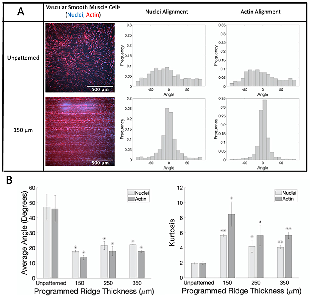
SMC show alignment when seeded on curved PDMS patterned with ridges compared to unpatterned samples. (A) Representative confocal microscopy images of SMC on curved PDMS with 150 μm ridges labeled for actin fibers (phalloidin, red) and nuclei (Hoechst, blue) with corresponding normalized alignment angle histograms. (B) Average absolute angles (0°–90°) for actin fibers and nuclei (left) and kurtosis of actin fibers and nuclei angle distributions (right). # p < 0.05, * p < 0.01, ** p < 0.001 compared to cells on curved unpatterned PDMS.(For interpretation of the references to color in this figure legend, the reader is referred to the web version of this article.)
3.3. GelMA patterning and cell alignment
We then determined whether FDM 3D printed molds could pattern hydrogels, which are both more physiologically relevant and more difficult to topographically pattern. Although the GelMA hydrogels were softer than the PDMS, the mold ridges transferred to the GelMA hydrogels with similar patterning efficiency for both flat and curved samples (Fig. 4; sample images in A; quantification in B). For all ridge sizes, the average measured GelMA ridge thickness was about 5% smaller than the programmed layer thickness, with a standard deviation of less than 10%.
Fig. 4.
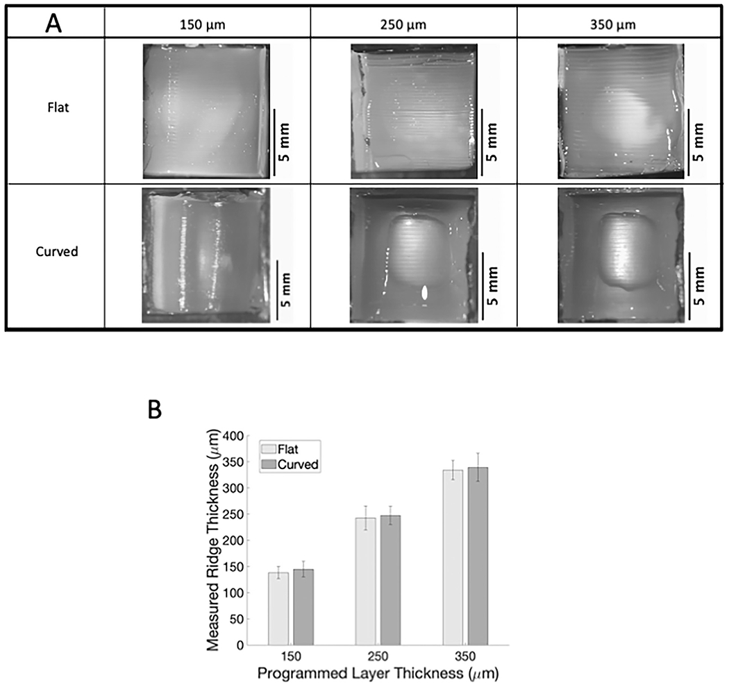
Ridge patterns on 3D printed molds can be successfully transferred to GelMA. (A) Images of flat and curved patterned GelMA acquired with Nikon SMZ745T. (B) Measured GelMA ridge thickness versus 3D printer programmed ridge thickness.
SMC seeded on flat patterned GelMA samples aligned in the ridge direction (Fig. 5; sample confocal microscopy images with corresponding nuclear and actin angle histograms in A; average angle and kurtosis for all samples in B). On flat, patterned GelMA of all ridge sizes, the average absolute angle of both nuclei and actin was around 30° and 20°, respectively, which was statistically significantly less than the average absolute nuclear and actin angles for SMC on unpatterned flat GelMA (p < 0.001). Similar results were observed for SMC on curved, patterned GelMA (Fig. 6; sample confocal microscopy images for unpatterned and 150 μm ridges with corresponding nuclear and actin angle histograms in A; average angle and kurtosis for all samples in B). SMC average nuclear and actin angles were statistically significantly lower, and angle distribution kurtoses were statistically significantly higher on curved patterned GelMA than on curved unpatterned GelMA. These data confirm that GelMA patterned with the ridges on FDM 3D printed molds can be used to align cells.
Fig. 5.
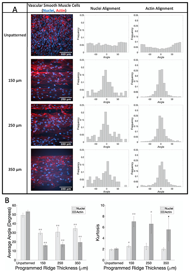
SMC show alignment when seeded on flat GelMA patterned with different ridge thicknesses compared to unpatterned samples. (A) Representative confocal microscopy images of SMC on flat GelMA labeled for actin fibers (phalloidin, red) and nuclei (Hoechst, blue) with corresponding normalized alignment angle histograms. (B) Average absolute angles (0°–90°) for actin fibers and nuclei (left) and kurtosis of actin fibers and nuclei angle distributions (right). # p < 0.05, * p < 0.01, ** p < 0.001 compared to cells on flat unpatterned GelMA.(For interpretation of the references to color in this figure legend, the reader is referred to the web version of this article.)
Fig. 6.
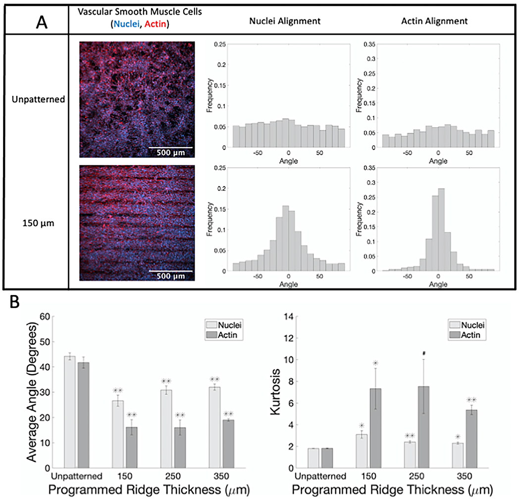
SMC show alignment when seeded on curved GelMA patterned with ridges compared to unpatterned samples. (A) Representative confocal microscopy images of SMC on curved GelMA labeled for actin fibers (phalloidin, red) and nuclei (Hoechst, blue) with corresponding normalized alignment angle histograms. (B) Average absolute angles (0°–90°) for actin fibers and nuclei (left) and kurtosis of actin fibers and nuclei angle distributions (right). #p < 0.05, * p < 0.01, ** p < 0.001 compared to cells on curved unpatterned GelMA.(For interpretation of the references to color in this figure legend, the reader is referred to the web version of this article.)
4. Discussion
Circumferential SMC alignment around a 3D cylindrical tube is essential for tissue engineering a blood vessel that can contract and relax. In this paper, we demonstrated a facile, low-cost method for creating ridges on flat and curved PDMS and GelMA structures using FDM 3D printed molds. SMC aligned with ridges of varying size on both substrate materials, independent of ridge size and substrate 3D shape. This method has potential to enable investigators to align different cell types on soft substrates and on a wide variety of 3D shapes for tissue engineering and other applications.
Pattern transfer from the 3D printed molds to PDMS was outstanding. While the smallest ridge size that we created was 150 μm, smaller ridges could be created with higher resolution printers. PDMS has been extensively topographically patterned with other molded structures, particularly silicon, for both cell culture and soft lithography [29]. 3D printed molds have significant advantages over silicon-based molds for patterning PDMS. Since ridges can be created on any shape surface, the interior of PDMS channels could be patterned, for example, to enhance mixing within a microfluidic device. Alternatively, channel-shaped stamps could be created out of PDMS to allow protein patterning within a microfluidic device. Since 3D printing is also inexpensive and fast, researchers could test different patterns without significant cost or lead time.
While PDMS topographical patterning has applications in microfluidics and cell culture experiments, hydrogels are more relevant for vascular tissue engineering. Pattern transfer from the 3D printed molds to the GelMA hydrogels resulted in slightly smaller ridges than on the PDMS substrates. Cell alignment was slightly lower on GelMA than on PDMS likely due to the ability of cells to pull on and deform the softer GelMA (~30 kPa). We used GelMA for these experiments since it is a cost-effective hydrogel with modifiable stiffness and the potential for functionalization with specific cell-adhesive ligands. We also applied this method to pattern collagen hydrogels with our 3D printed molds, suggesting that this technique should work on most hydrogels as long as they are of adequate stiffness to maintain the topographical structure once the mold is removed.
A primary advantage of this technique is the ability to pattern 3D surfaces. We demonstrated this on 10 mm diameter semi-cylindrical surfaces here; in other studies, we created semi-cylindrical molds down to 2 mm diameter and even smaller structures could likely be created with a higher resolution printer. To create a cylindrical channel structure, two PDMS or hydrogel semi-cylinders could be patterned and then bonded together as described in other studies [26]. Alternatively, a dissolvable filament such as polyvinyl alcohol (PVA) could be used to create the ridged cylindrical mold. This technique did pattern ridges on the inside of PDMS and GelMA cylindrical channels; however, the PVA prevented cell adhesion to the channel surface, therefore alternative dissolvable materials should be used if cell adhesion is desired.
5. Conclusions
In this paper, we now demonstrate a rapid, cost-effective way to pattern topographical ridges onto both flat and curved PDMS and GelMA using FDM 3D printed molds. SMC seeded onto the topographically patterned substrates aligned with the ridge long axes. This technique can be applied to pattern 3D surfaces of polymers and hydrogels and thereby align a variety of cell types for tissue engineering applications.
Funding statement
This work was supported by the National Institutes of Health [grant number R21EB028466] and the National Science Foundation [grant number CBET 1916997.]
Footnotes
Declaration of Competing Interest
The authors declare that they have no known competing financial interests or personal relationships that could have appeared to influence the work reported in this paper.
References
- [1].Li Y, et al. , Engineering cell alignment in vitro, Biotechnol. Adv 32 (2) (2014) 347–365. [DOI] [PubMed] [Google Scholar]
- [2].Dartsch PC, Hammerle H, Orientation response of arterial smooth muscle cells to mechanical stimulation, Eur. J. Cell Biol 41 (2) (1986) 339–346. [PubMed] [Google Scholar]
- [3].Zhao M, et al. , Electrical stimulation directly induces pre-angiogenic responses in vascular endothelial cells by signaling through VEGF receptors, J. Cell Sci 117 (Pt 3) (2004) 397–405. [DOI] [PMC free article] [PubMed] [Google Scholar]
- [4].Steward R Jr., et al. , Fluid shear, intercellular stress, and endothelial cell alignment. 2015. 308(8): p. C657–C664. [DOI] [PMC free article] [PubMed] [Google Scholar]
- [5].Kemeny SF, et al. , Glycated collagen alters endothelial cell actin alignment and nitric oxide release in response to fluid shear stress, J. Biomech 44 (10) (2011) 1927–1935. [DOI] [PubMed] [Google Scholar]
- [6].Greiner AM, et al. , Cyclic tensile strain controls cell shape and directs actin stress fiber formation and focal adhesion alignment in spreading cells, PLoS One 8 (10) (2013) e77328. [DOI] [PMC free article] [PubMed] [Google Scholar]
- [7].Figueroa DS, Kemeny SF, Clyne AM, Glycated collagen decreased endothelial cell fibronectin alignment in response to cyclic stretch via interruption of actin alignment, J. Biomech. Eng 136 (10) (2014) 101010. [DOI] [PubMed] [Google Scholar]
- [8].Nakamoto T, et al. , Influence of micropattern width on differentiation of human mesenchymal stem cells to vascular smooth muscle cells, Colloids Surf. B Biointerfaces 122 (2014) 316–323. [DOI] [PubMed] [Google Scholar]
- [9].Folch A, Toner M, Cellular micropatterns on biocompatible materials, Biotechnol. Prog 14 (3) (1998) 388–392. [DOI] [PubMed] [Google Scholar]
- [10].Biela SA, et al. , Different sensitivity of human endothelial cells, smooth muscle cells and fibroblasts to topography in the nano-micro range, Acta Biomater 5 (7) (2009) 2460–2466. [DOI] [PubMed] [Google Scholar]
- [11].Li J, et al. , Engineering micropatterned surfaces to modulate the function of vascular stem cells, Biochem. Biophys. Res. Commun 444 (4) (2014) 562–567. [DOI] [PubMed] [Google Scholar]
- [12].Agrawal A, et al. , Smooth muscle cell alignment and phenotype control by melt spun polycaprolactone fibers for seeding of tissue engineered blood vessels, Int. J. Biomater 2015 (2015) 434876. [DOI] [PMC free article] [PubMed] [Google Scholar]
- [13].Thakar RG, et al. , Regulation of vascular smooth muscle cells by micropatterning, Biochem. Biophys. Res. Commun 307 (4) (2003) 883–890. [DOI] [PubMed] [Google Scholar]
- [14].Goessl A, Bowen-Pope DF, Hoffman AS, Control of shape and size of vascular smooth muscle cells in vitro by plasma lithography, J. Biomed. Mater. Res 57 (1) (2001) 15–24. [DOI] [PubMed] [Google Scholar]
- [15].Thakar RG, et al. , Cell-shape regulation of smooth muscle cell proliferation, Biophys. J 96 (8) (2009) 3423–3432. [DOI] [PMC free article] [PubMed] [Google Scholar]
- [16].Williams C, et al. , The use of micropatterning to control smooth muscle myosin heavy chain expression and limit the response to transforming growth factor beta1 in vascular smooth muscle cells, Biomaterials 32 (2) (2011) 410–418. [DOI] [PMC free article] [PubMed] [Google Scholar]
- [17].Sarkar S, et al. , Vascular tissue engineering: microtextured scaffold templates to control organization of vascular smooth muscle cells and extracellular matrix, Acta Biomater. 1 (1) (2005) 93–100. [DOI] [PubMed] [Google Scholar]
- [18].Shen JY, et al. , Three-dimensional microchannels i n biodegradable polymeric films for control orientation and phenotype of vascular smooth muscle cells, Tissue Eng. 12 (8) (2006) 2229–2240. [DOI] [PubMed] [Google Scholar]
- [19].Glawe JD, et al. , Influence of channel width on alignment of smooth muscle cells by high-aspect-ratio microfabricated elastomeric cell culture scaffolds, J. Biomed. Mater. Res. A 75 (1) (2005) 106–114. [DOI] [PubMed] [Google Scholar]
- [20].Cao Y, et al. , Regulating orientation and phenotype of primary vascular smooth muscle cells by biodegradable films patterned with arrays of microchannels and discontinuous microwalls, Biomaterials 31 (24) (2010) 6228–6238. [DOI] [PubMed] [Google Scholar]
- [21].Tijore A, et al. , Bioprinted gelatin hydrogel platform promotes smooth muscle cell contractile phenotype maintenance, Biomed. Microdev 20 (2) (2018) 32. [DOI] [PubMed] [Google Scholar]
- [22].Canver AC, et al. , Endothelial directed collective migration depends on substrate stiffness via localized myosin contractility and cell-matrix interactions, J. Biomech 49 (8) (2016) 1369–1380. [DOI] [PubMed] [Google Scholar]
- [23].Chen M, et al. , Temperature Responsive Shape-Memory Scaffolds with Circumferentially Aligned Nanofibers for Guiding Smooth Muscle Cell Behavior, Macromol Biosci 20 (2) (2020) e1900312. [DOI] [PubMed] [Google Scholar]
- [24].Ebrahimi M , et al. , Enhanced skeletal muscle formation on microfluidic spun gelatin methacryloyl (GelMA) fibres using surface patterning and agrin treatment, J. Tissue Eng. Regen. Med 12 (11) (2018) 2151–2163. [DOI] [PubMed] [Google Scholar]
- [25].Wu P, et al. , Construction of vascular graft with circumferentially oriented microchannels for improving artery regeneration, Biomaterials 242 (2020) 119922. [DOI] [PMC free article] [PubMed] [Google Scholar]
- [26].Choi JS, Piao Y, Seo TS, Circumferential alignment of vascular smooth muscle cells in a circular microfluidic channel, Biomaterials 35 (1) (2014) 63–70. [DOI] [PubMed] [Google Scholar]
- [27].Fomovsky GM and Holmes JW, Evolution of scar structure, mechanics, and ventricular function after myocardial infarction in the rat. 2010. 298(1): p. H221–H28. [DOI] [PMC free article] [PubMed] [Google Scholar]
- [28].Karlon WJ, et al. , Automated measurement of myofiber disarray i n transgenic mice with ventricular expression of RAS, Anat. Rec 252 (4) (1998) 612–625. [DOI] [PubMed] [Google Scholar]
- [29].Sousa MP, et al. , Surface micro- and nanoengineering: applications of layer-by-layer technology as a versatile tool to control cellular behavior, Small 15 (30) (2019) e1901228. [DOI] [PubMed] [Google Scholar]


