Fig. 1.
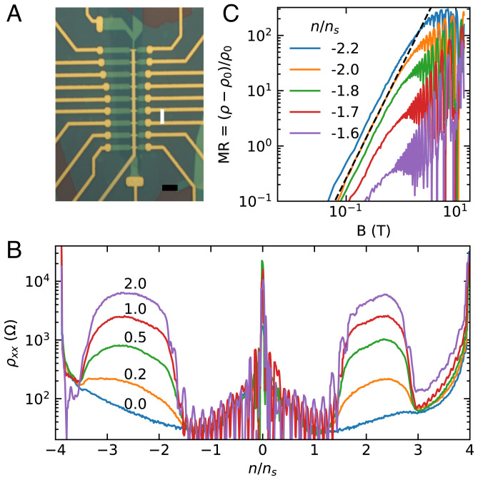
Low-field magnetotransport. (A) Optical micrograph of the device showing contacts and top gate in gold and hBN in green. We use the large top and bottom contacts to source and drain current. The channel width is 1 µm, and all longitudinal contact pairs are separated by three squares. The white line indicates the contact pair that we study throughout this work. (Scale bar: 5 µm.) (B) Longitudinal resistivity of the device as density is tuned through empty to full moiré cell at several fixed magnetic fields (in Tesla). The peak at n = 0 is charge neutrality, and the peaks at the edges of the plot are full filling/emptying of the moiré unit cell. At nonzero fields, there are regions on either side of charge neutrality with large, positive magnetoresistance. (C) Magnetoresistance ratio as a function of field for several fixed densities on a log-log plot. Each trace is offset vertically for clarity. The black dashed line is a quadratic.

