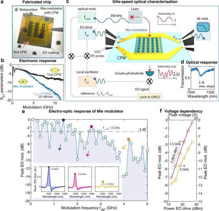
Fig. 4. GHz-speed properties of the Mie modulators.
a Picture of a fabricated chip shows Mie modulators that are integrated with GHz coplanar waveguides (CPW). Also visible are test CPW. b Electronic scattering parameters S21 of Mie modulators are compared to test CPW. The S21 are measured using a vector network analyzer (VNA) connected to the sample by high-frequency cables and high-speed microwave GSG (ground-source-ground) probes (one ground floating) and exhibits a cut-off of f−6dB = 4.2 GHz owing to the intrinsic RC bandwidth. RF cable losses are deducted from the S21 response. Beyond 4.2 GHz, only the Mie modulators exhibit a decay of –20 dB/decade (much less steep roll-over for the test CPW). c Optoelectronic experimental setup. The electronic characteristics are measured in a transmission configuration using the VNA, and the wavelength-resolved electro-optical (EO) modulation is measured using a lock-in amplifier. A double modulation scheme combined with a local oscillator (LO) is used, where the laser emission is modulated at the source and the Mie modulators (details in the methods) are actuated electronically by the RF source. d Resonance of sample (hSiO2 = 200 nm, θ = 25°). e Peak electro-optic modulation amplitude for frequencies fRF up to 5 GHz. We find a 3-dB electro-optic bandwidth of fEO,−3dB = 3 GHz. Insets: wavelength-resolved modulation strength for several values of fRF, the peak values have been utilized to plot the data in e. f Peak electro-optic modulation amplitude for different modulation voltages (reported as power in dBm), at 1.5 and 5 GHz, the latter well beyond the electro-optic bandwidth.

