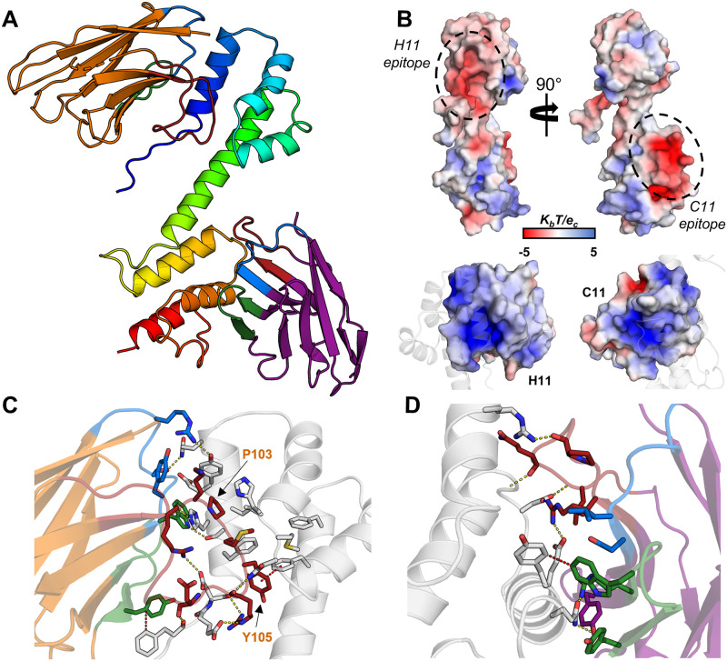
Fig 7. The crystal structure of rArc-CTD in complex with NbArc-H11 and -C11.
A The overall structure. The CTD of rArc is shown in blue to red from the N- to the C-terminus. NbArc-H11 is shown in orange and NbArc-C11 in purple. CDR 1, 2, and 3 are coloured blue, green, and red, respectively. B Both Nbs bind acidic surface patches of the CTD (above); the surface of the Nb CDRs is positive (below). Electrostatic potential was calculated using ABPS [76]. The epitopes correspond to the ligand peptide binding site of the N-lobe (H11) and the C-lobe oligomerisation surface (C11). C Pro103 and Tyr105 of H11 extend into the Arc N-lobe hydrophobic pocket. D C11 binding of the rArc-CTD. Polar contacts (yellow) and π-π interactions (red) are indicated with dashes.

