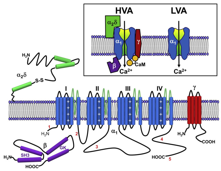
Figure 4.
Representation of the membrane topology and secondary structure of HVA channels. In blue: the common structure of HVA and LVA channels, with their four VSD (I, II, III, and IV). The dark blue cylinder in each VSD is the charged S4 helix. The single blue cylinder in each VSD is the S6 helix that forms the pore domain. In green, purple, and red: the other subunits of HVA channel. The lengths of lines correspond approximately to the lengths of the polypeptide segments represented. Inbox at top: comparative representation of the structure of HVA and LVA calcium channels () and the subunits of HVA channels (, , and ). Taken from the journal Neuron, article “Neuronal Voltage-Gated Calcium Channels: Structure, Function, and Dysfunction” [184].

