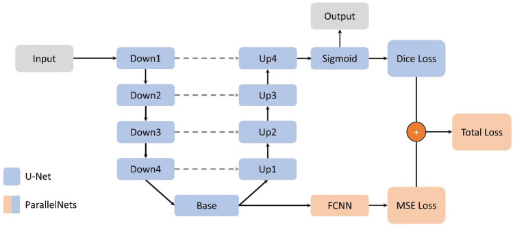
Figure 1.
Schematic ParallelNets architecture. The classical U-Net architecture21 with four encoder blocks (Down) and four decoder blocks (Up) connected by a base block (Base) is shown in blue. Encoder and decoder blocks of the same level are connected by skip connections (gray dashed lines). The additional modules of our ParallelNets architecture are shown in orange and basically consist of a fully connected neural network (FCNN) which is trained to output the crack tip position in terms of normalized x and y coordinates.

