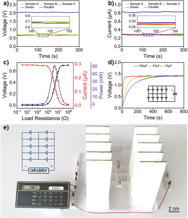
Figure 5.

Output performance and applications of the LS‐TENG. a) V oc and b) I sc of an individual sample, and three samples in series or parallel. c) Output voltage, current, and power of the LS‐TENG with different load resistances. d) The LS‐TENGs charging the capacitors of 100, 47, and 10 µF. Inset: circuit diagram. e) Photograph of the LS‐TENGs powering an electronic calculator. Inset: circuit diagram. All experiments in this figure were conducted with LS‐TENGs sized 40×130×1 mm3 at room relative humidity ≈50.0% and temperature ≈27.0 °C.
