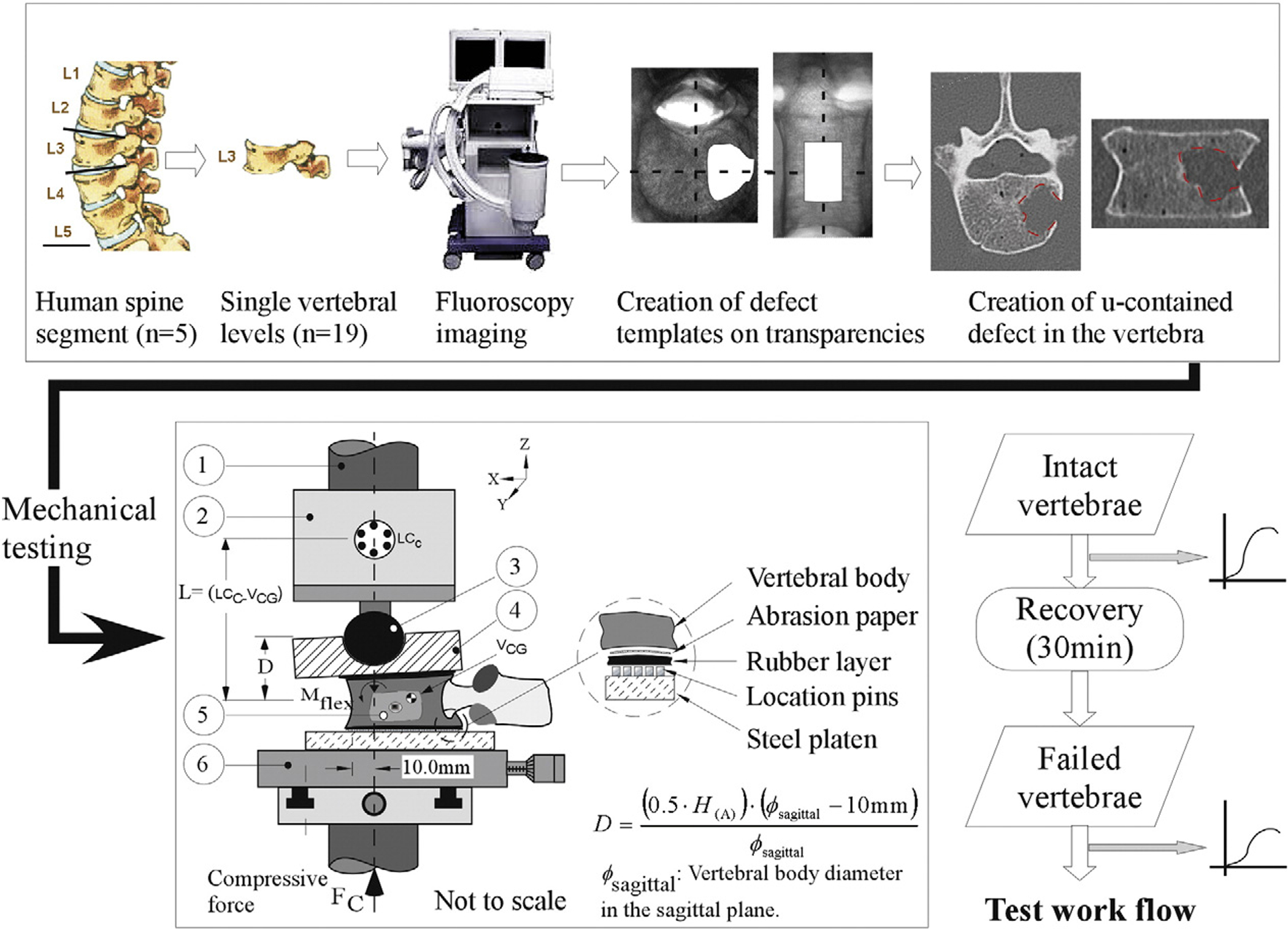
Fig. 1.

A schematic diagram of the testing device used to apply combined compression and flexion loads onto the vertebral specimens. 3 mm rubber sheets located on either side of the vertebra allowed a more uniform transfer of load between the test device and the vertebra. Coarse-grit sandpaper, bonded on the outer side of the rubber sheets (Fig. 1) provided containment of the vertebra to the testing assembly whilst keeping the strengthening effect of cement embedding of the vertebra on the resulting vertebral deformations to a minimum. Required test displacement at the actuator, D, of the material testing system was computed from the equation (Alkalay et al., 2008) with (H(A)): anterior height of the vertebra (intact, failed), Ø sagittal: the sagittal diameter of the upper endplate measured from the X-rays.
