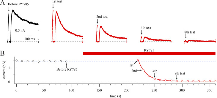
Figure 2.
Voltage stimuli are required for RY785 to inhibit Kv2.1. (A) Current traces from a representative cell in vehicle (black) or 1 µM RY785 (red). Voltage protocol from a holding potential of −100 mV is a 20-ms step to +40 mV followed by a 30-ms step to −100 mV and then a 500-ms step to +40 mV. Arrows indicate time points labeled in B. (B) Mean current in the final 1 ms of the 20-ms test pulse (circles). Red bar indicates application of 1 µM RY785. Currents in RY785 are fitted with an exponential function (Eq. 4, red curve). Function variables ± SD, y0 = 0.0482 ± 0.0039 nA, A = 1.533 ± 0.012 nA, τ = 14.40 ± 0.24 s. Dotted blue line indicates steady state current before RY785 application.

