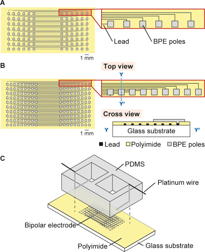
Figure 2.

Devices with an array of BPEs. Electrode layouts of (A) type I device with arrays of 6 × 8 cathodic and anodic poles and (B) type II device with arrays of 9 × 10 cathodic and anodic poles. Cross section along the Y–Y′ line is shown on the bottom right of panel B. (C) Experimental setup with the BPEs on a glass substrate and PDMS chambers with driving electrodes placed atop the glass substrate.
