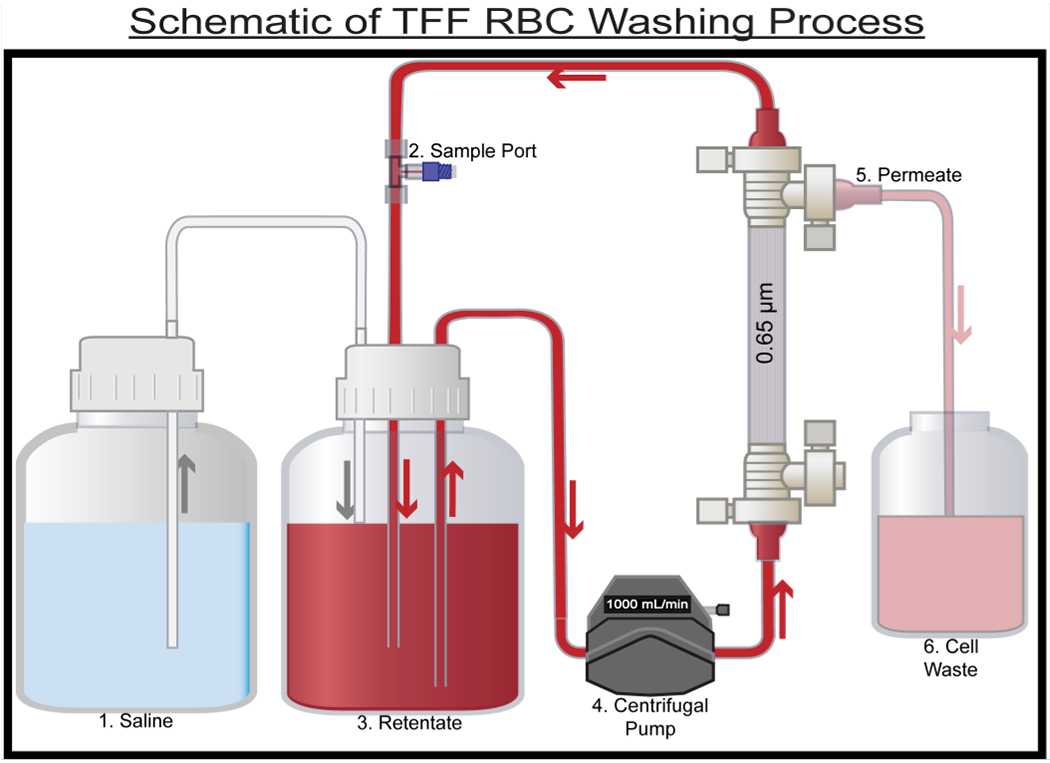
Figure 1:

Process flow diagram for the RBC washing process. 10 single RBC units were processed using the TFF RBC washing system.(1) Reservoir containing 0.9 wt% saline.(2) Sample port used for retentate sampling. (3) Retentate vessel, 0.65 μm TFF filter used to wash RBCs. (4) Centrifugal pump. (5) Permeate waste from the process (contains species < 0.65 μm in size). (6) Cell waste. Arrows indicate the direction of flow.
