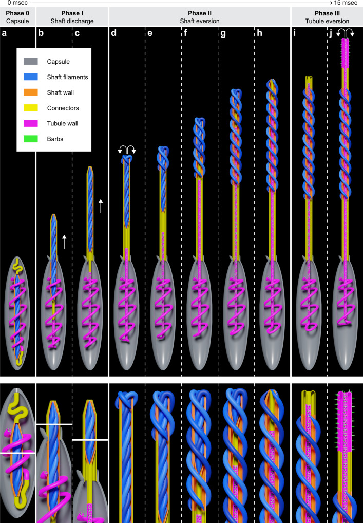
Fig. 4. Model of the geometric transformation of the shaft and tubule.
The box indicates the sub-structures of the nematocyst. Lower panels: Magnified views of critical regions during distinct phases. a Undischarged capsule with tightly coiled shaft surrounded by the shaft wall, two connectors, and the coiled tubule. b, c Initial stage of shaft discharge (Phase I). The forward movement and eversion of the capsule-shaft (CS) connector enclosing the ejected shaft filaments are shown. The arrows indicate the forward movement of the shaft. d–h The geometric eversion mechanism of the shaft and uncoiling of the compressed shaft filaments (Phase II). Arrows indicate the direction of the forces applied to the apex of the compressed shaft filaments. e–g Steps in the progression of shaft eversion. The model shows the uncoiling shaft filaments and the forward movement of the shaft-tubule connector and the tubule. h The final stage of shaft eversion. Note: The basal end of the uneverted shaft becomes the apical end of the everted shaft. i–j The eversion mechanism of the shaft-tubule connector and the tubule (Phase 3).

