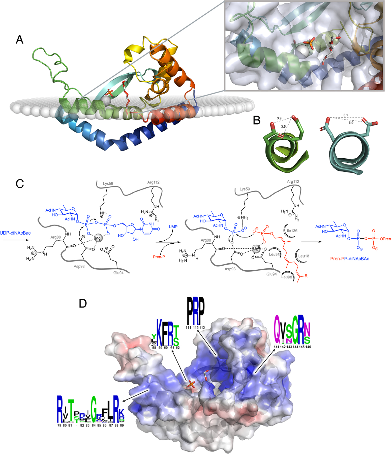
Figure 5. Structure and mechanism of the monoPGTs.

A. Ribbon diagram of monoPGT PglC (PDB 5W7L) color ramped from N- to C- terminus (blue to red shown in membrane as calculated using the OPM server (43) with Mg2+ ion (grey sphere), phosphate and PEG (white stick; PEG molecule shows proposed position for UndP binding). Inset shows close-up view of active site with protein transparent surface. B. Active-site helix 310-geometry allows for co-facial positioning of Asp-Glu catalytic dyad. MonoPGT PglC residues 91–99 shown in ribbon representations colored as in panel A with side chains of the catalytic dyad Asp93-Glu94 shown as stick. PolyPGT DPAGT1 (PDB 6FWZ) residues 100–118 shown in ribbon representation colored as in Figure 4A with residues Asp115 and Asp116 from the conserved aspartyl motif shown as stick. In polyPGTs these residues do not play an analogous role in catalysis (see text). Shortest distances between oxygen atoms on proximal residues (gray dashed lines). C. Bi-Bi ping-pong mechanism of monoPGTs with proposed roles for binding and catalytic residues (numbering from Campylobacter concisus PglC). D. Electrostatic mapping of PglC revealing positive funnel for substrate binding. Ribbon diagram of PglC with transparent surface colored by electrostatic potential ramped from −5 kT/e (red) to 5 kT/e (blue). Ligands shown as in panel A. The sequence conservation of positive pockets was calculated using sequences of all three classes of monoPGT (small, large, and bifunctional), visualized using WebLogo (C. concisus PglC numbering).
