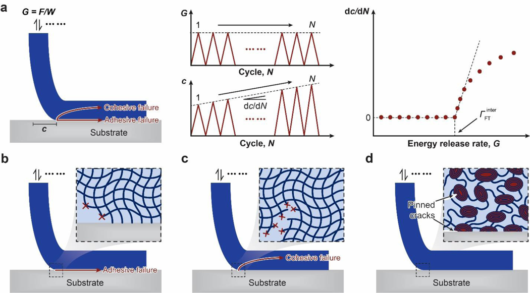
Figure 21. Design principle for fatigue-resistant adhesion of hydrogels – strongly bond intrinsically high-energy phases on interfaces:
a. definition of interfacial fatigue threshold and the 90-degree cyclic peeling test to measure the interfacial fatigue threshold. F is the applied peeling force, W is the width of the sample, G is the energy release rate, c is the crack length, and N is the cycle number. The interfacial fatigue threshold is determined by intersecting the curve of dc / dN vs G with the G axis. b. fatigue-crack propagation along the interface giving adhesive failure. c. fatigue-crack propagation in the hydrogel giving cohesive failure. d. fatigue-crack pinned by intrinsically high-energy phases on the interface and in the bulk hydrogel71. d is adopted from Ref71.

