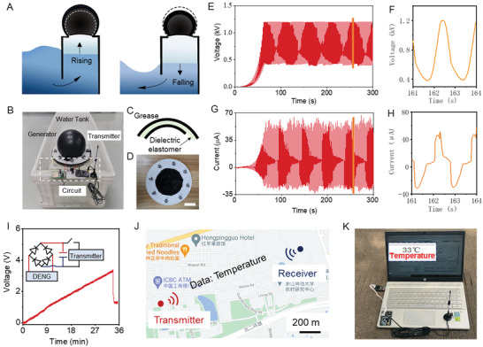
Figure 4.

Illustration of the self‐powered remote temperature reading system. A) Schematic illustration of the WEH. The water column falls and rises periodically as water waves, causing the DEC to inflate and deflate in cycles. B) Photo image of the intergraded device of WEH and remote temperature transmitting circuit. C) Structural schematic and D) optical photograph of the DEC amounted on the OWH. Scale bar: 6.5 cm. E) Output voltage and G) output current of WEH at an agitation frequency of 0.5 Hz. F) Enlarged output voltage and H) enlarged output current of WEH at an agitation frequency of 0.5 Hz. I) Voltage variation of the capacitor (2.2 mF) in consequent remote temperature reading system processes. J) The schematic of the distance temperature transmission of the communication nodes on the ZJNU campus using the wave energy. K) Receiver node of self‐powered remote temperature reading system. A computer interface showing the successful transmission of the temperature information.
