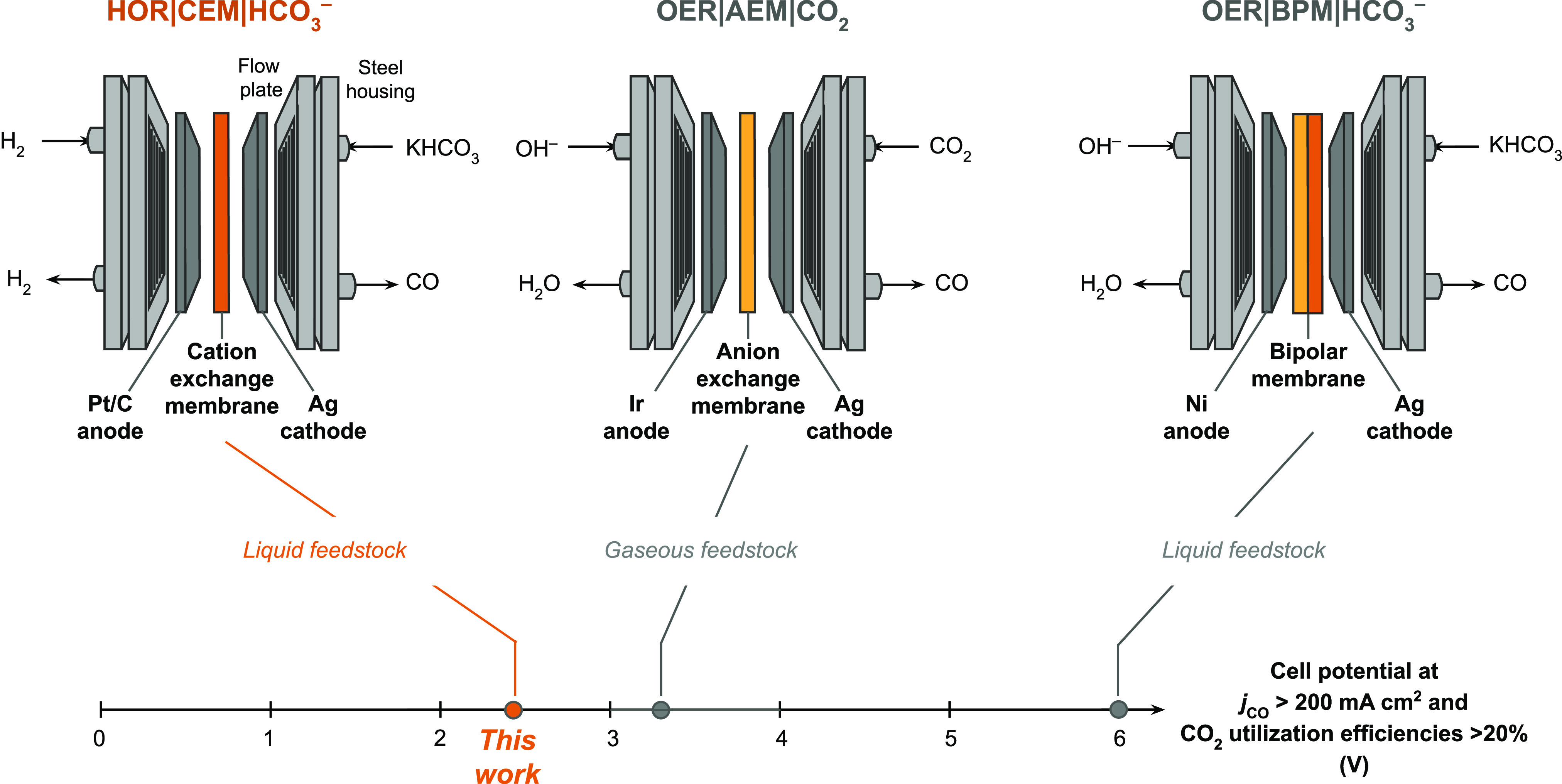
Figure 1.

Schematics and nomenclature of prototypical CO2 to CO electrolyzer configurations. The electrolyzer reported in this work is HOR|CEM|HCO3–, which uses a reactive carbon solution feedstock, a cation exchange membrane (CEM), and hydrogen oxidation at the anode to achieve low voltages and high CO2 utilization efficiencies. The OER|AEM|CO2 electrolyzer is a widely used architecture that uses a gaseous CO2 feedstock. The OER|BPM|HCO3– electrolyzer also uses a reactive carbon solution feedstock, but the BPM needs to be optimized to achieve lower applied cell voltages. The lowest cell voltages reported in the literature for each electrolyzer architecture are indicated, but only the electrolyzers that produce jCO >200 mA cm–2 and CO2 utilization efficiency >20% are considered.9,19 The nomenclature follows “anode|membrane|cathode”.
