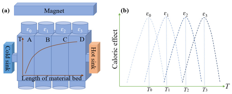
Figure 5.
(a) The schematic diagram of the temperature gradient in the material bed, where the temperature gradient is displayed, where T indicate the temperature of the refrigerates and A, B, C, D indicate refrigerants at four different positions in the material bed. (b) The optimal working temperature of refrigerants tuned by the uniaxial strain.

