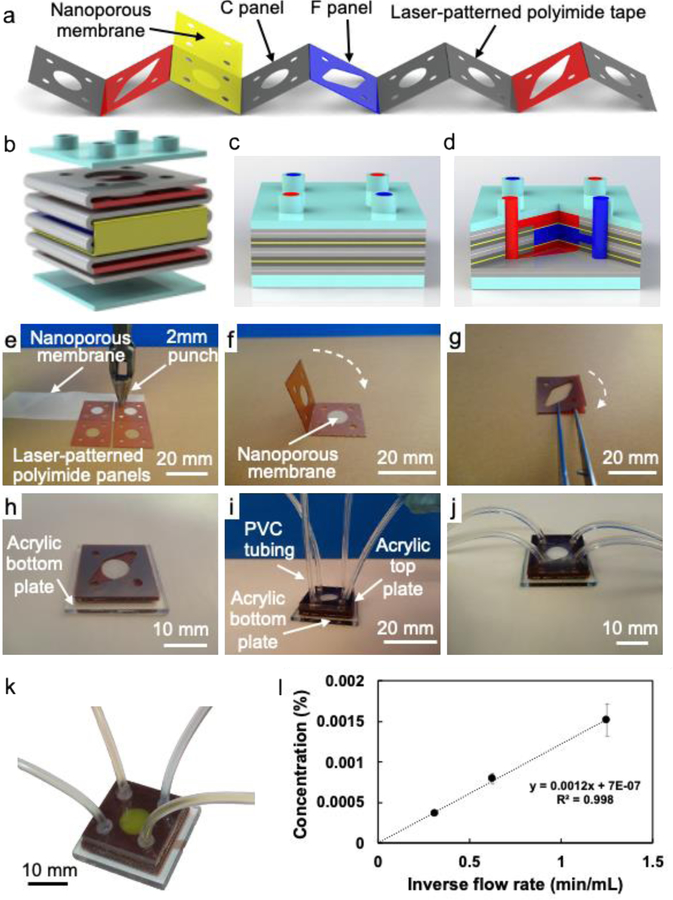
Figure 2.
(a) Schematic diagram of the laser-patterned polyimide tape and nanoporous membrane oriented for cross-folding; (b) exploded schematic diagram of the folded structure of the oLOC (gray, red, dark blue, and yellow) and its top and bottom acrylic caps (light blue); (c) schematic and (d) cross-sectional cutaway diagrams of the completed oLOC; (e - j) photographs showing the fabrication process for the Generation 3 devices, including (e) hole punching and trimming to pattern the nanoporous membrane, (f) folding the nanoporous membrane between chamber panels to form origami sub-units, (g) layering flow panels to form additional sub-units, (h) stacking the origami sub-units on top of the solid acrylic base plate to form the device’s flow structure, (i) capping the stack with an acrylic top plate (laser-cut with four inlet/outlet ports) and adhering PVC tubing into ports, and (j) final Generation 3 device structure after assembly; (k) flow pattern of Generation 3 device shown by flowing yellow dye through the simulated sinusoids and blue dye through the hepatocyte chambers; (l) plot of concentration of trypan blue in the flow exiting the middle flow path as a function of inverse flow rate when a 0.1% solution of trypan blue in deionized water is flowed through a chip’s upper and lower flow paths and deionized water is flowed through its middle flow path with no pressure difference between flow paths.

