
Figure 5: Device characterization and in vitro validation of the fully viscoelastic device.
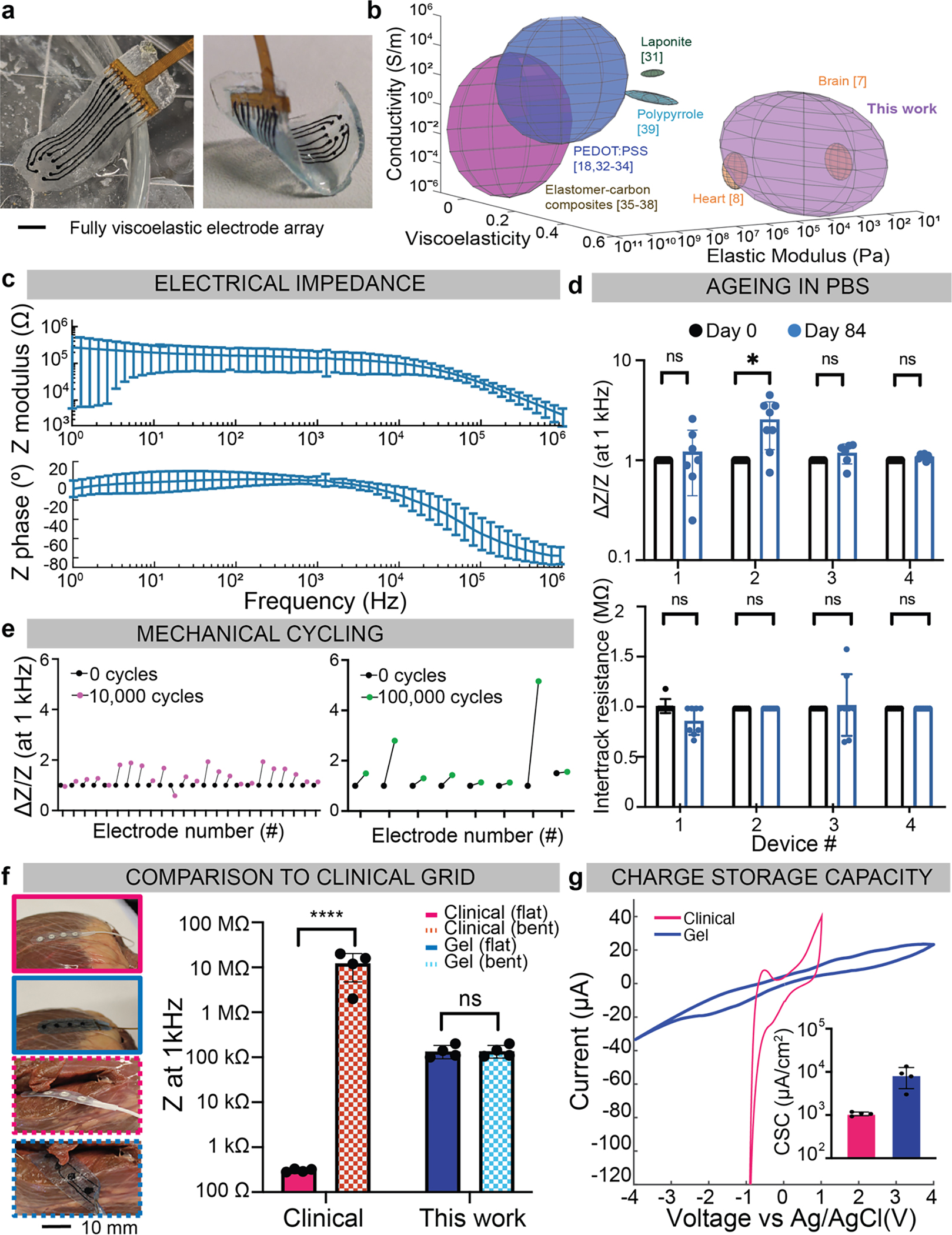
(a) Photographs of the fully assembled array, 6 mm × 20 mm × 250 μm, with 8 electrodes of d=700 μm and a 1.5 mm pitch, flat in PBS (left), and bent (right). Scale bar represents 3 mm.
(b) Quantification of the elastic modulus (Pascals), conductivity (S/m), and viscoelasticity (tan(δ)), of various tissues and conductive composites. Rat heart and brain tissue in orange, represent the targeted physiologic stiffness and viscoelasticity. The alginate-based conductors fabricated in this study are shown in purple. Values for other conductive composites reported in the literature are also represented, using the reported ranges for each variable. Citations are provided for the values in the illustration, which are taken from the literature in Supplementary Table 2.
(c) Electrical impedance spectroscopy (EIS) data of five devices, from five distinct batches, measured in PBS showing the impedance modulus (left) and impedance phase (right) over a frequency sweep from 1 MHz to 1 Hz. Mean and s.d. of each device plotted, over n=40 of the electrodes.
(d) Comparison of electrode impedance of 4 arrays at 1 kHz, before and after ageing in PBS for 84 days (top). Impedance for each electrode is normalized to the impedance value before ageing. Intertrack resistance between adjacent electrodes, plotted before and after ageing in PBS (bottom), for n=4 independent devices. Numerical data presented as mean ± s.d. (one-way ANOVA and Tukey’s HSD post hoc test, *p<0.05 (p=0.02) and non-significant, n.s., p>0.05.
(e) Multiaxial mechanical cycling of viscoelastic arrays, at an equivalent 11% biaxial strain, with the relative change in impedance (DZ/Z) at 1 kHz plotted for each electrode. Three devices were cycled 10,000 times (left, pink) and one device was cycled 100,000 times (right, green).
(f) Photographs of a commercial clinical grid (pink) with a similar-dimensioned viscoelastic array (blue), on a bovine heart (left). Scale bar represents 10 mm. The grids were placed on smooth regions of the tissue (solid line) and bent 90° around the heart (dashed lines). Impedance at 1 kHz is extracted for each electrode (n=4/device) and compared for the flat and bent configurations (right). Mean and s.d. are plotted, with ****p<0.0001 and non-significant, n.s., p>0.05.
(g) Cyclic voltammetry of an electrode from the commercial grid (pink), and from the viscoelastic array described in this work (blue). Inset bar graph shows the charge storage capacity (CSC) extracted from each electrode (n=4/device) and compared over the four electrodes from each array (inset). Mean and s.d. of each electrode plotted.