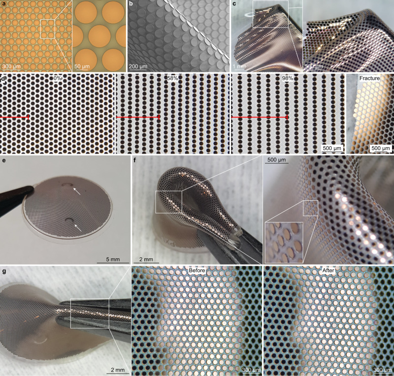
Fig. 4. Optimisation of the POLYRETINA device.
a Picture of the photovoltaic pixels (100-µm diameter and 120-µm pitch). b Scanning electron microscopy picture of the photovoltaic pixels released from the wafer and folded to obtain tilted views on the pixels. c Image of a photovoltaic interface stretched and wrinkled with tweezers. d Pictures of the photovoltaic interface taken at 0, 54 and 98% of strain, and after fracture during a stretching test. The red bar shows six rows of pixels in the stretching direction. e Picture of a POLYRETINA. The white arrows indicate the points where tacks will be inserted. f Picture of a POLYRETINA folded four times. Images at various magnifications show that the photovoltaic pixels are intact during folding. g Picture of a POLYRETINA during pinching with magnifications on the intact photovoltaic pixels before and after pinching. Experiments in panels d, f–g have been reproduced in three replicates.

