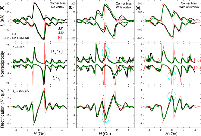
Fig. 4. Diode operation on D1 with the right-corner bias.
a Without a vortex, b with a trapped vortex, and c with an antivortex. Top panels show the Ic(H) modulations. Middle panels show the nonreciprocities, ∣Ic+/Ic−∣, upper curves, and Ic−/Ic+, lower curves. Bottom panels show rectified dc-voltage calculated for harmonic ac-bias with Iac = 220 μA ≃ Ic0. Black and olive lines represent data for junctions 1 and 2 on D1, red lines are numerical fits. Appearance of a profound nonreciprocity and rectification at H = 0 is marked by cyan circles in b, c. All measurements are performed at T ≃ 6.9 K.

